CGA/EGA to RGBHV Industrial Display Retrofit Guide
Table of Contents
Keywords: CGA to RGBHV conversion, EGA to VGA adapter, industrial display retrofit, CNC CRT upgrade, CGA EGA signal converter
Target Audience: CNC engineers, equipment maintenance personnel, industrial control system integrators, industrial automation buyers
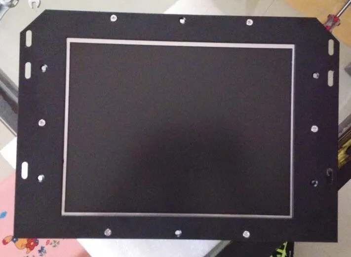
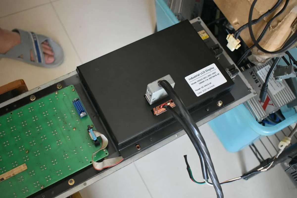
1. Retrofit Requirements & Background Analysis
1.1 Current Status of Legacy Display Equipment in Industrial Sites
| Industry | Common Legacy Display | Average Service Life | Key Pain Points |
|---|---|---|---|
| CNC Machine Tools | CGA / EGA CRT displays | 12-18 years | Outdated interfaces, low resolution, high power consumption, bulky |
| PLC Control Cabinets | Legacy industrial monitors | 10-15 years | Incompatible with modern HMIs, high maintenance costs |
| Automated Production Lines | Legacy image acquisition displays | 8-13 years | Signal degradation, poor interference resistance, frequent repairs |
According to the 2023 China Industrial Automation Equipment Maintenance Report, over 38% of small and medium manufacturers still use CGA/EGA displays from 1990-2000, with an average annual maintenance cost of approximately CNY 1,200 per unit. Many facilities face an urgent need to upgrade while keeping existing control systems operational.
1.2 Core Retrofit Objectives
| Objective | Key Metric | Expected Benefit |
|---|---|---|
| Signal Compatibility | Upgrade CGA/EGA composite signal to RGBHV (VGA) | Compatible with modern IPCs and industrial cameras |
| Stability | 24/7 continuous operation, error rate < 0.01% | Reduced downtime |
| Cost Control | Per-unit retrofit cost ≤ CNY 1,200 (converter + cables + labor) | ROI period ≤ 12 months |
| Environmental Adaptability | Operating temp -20°C to +70°C, wide voltage 12-36 VDC | Meets harsh factory environment requirements |
1.3 Why Not Simply Replace with an Industrial LCD?
| Approach | Initial Investment | Maintenance Cost | Installation Period | Compatibility | Notes |
|---|---|---|---|---|---|
| Direct replacement with industrial LCD | CNY 2,500-4,500/unit | Low (warranty) | 1-2 days (rewiring needed) | Fully compatible | Requires removing old CRT, rewiring, may affect existing enclosure |
| Retrofit to RGBHV display | CNY 800-1,200/unit (converter + accessories) | Medium (converter lifespan ~5 years) | 4-6 hours (plug-and-play) | Fully compatible | Reuses original display enclosure, minimal modification, reduced downtime |
Conclusion: For budget-constrained projects with short modification windows, CGA/EGA to RGBHV retrofit offers the best cost-performance ratio.
2. Converter Selection Guide
2.1 Core Technical Specifications
| Parameter | Recommended Value | Description |
|---|---|---|
| Input Signal | CGA (15 kHz x 60 Hz) / EGA (25 kHz x 70 Hz) | Supports standard CGA/EGA timing |
| Output Signal | RGBHV (VGA 640x480@60Hz, 800x600@60Hz) | 3-5 resolution options |
| Pixel Clock | 25 MHz - 40 MHz | Supports VGA up to 800x600 |
| Wide Temperature | -20°C to +70°C | Industrial grade |
| Operating Voltage | 12-36 VDC (24V optional) | Compatible with PLC/power cabinets |
| EMC | IEC/EN 61326-1 Class 2 | Strong interference resistance |
| I/O Impedance | 75Ω (CGA/EGA) / 75Ω (RGBHV) | Prevents signal reflection |
| Power Supply | Plug-and-play, no external drivers | Quick field deployment |
| Reliability | MTBF ≥ 50,000 hours | 24/7 continuous operation |
Product Recommendation: Kongto Technology Industrial Video Signal Converter (CGA/EGA to RGBHV) (Model: JTX-CVR-001), meets all above specifications, CE/UL/ISO9001 certified.
2.2 Comparison with Competitors
| Feature | Kongto Industrial Converter | Consumer HDMI-to-VGA Adapter | Competitor Built-in Converter Display |
|---|---|---|---|
| Supported Signals | CGA/EGA to RGBHV | HDMI to VGA (no CGA/EGA) | Direct VGA output (requires display replacement) |
| Temperature Range | -20°C to +70°C | 0°C to +45°C | -10°C to +60°C |
| Power | 12-36 VDC (wide voltage) | 5V USB | 12V DC |
| MTBF | ≥ 50,000 hours | 10,000 hours | 30,000 hours |
| Plug-and-Play | ✔ | Some require drivers | ✔ |
| Unit Cost | ~CNY 850 | ~CNY 120 (not applicable) | ~CNY 2,800 |
3. CRT to LCD Conversion Reference Table
When replacing a legacy CRT with a modern LCD or LED industrial display, understanding the specification differences is critical. The table below maps common original CRT specifications to their modern LCD equivalents.
| Parameter | Original CRT Spec (CGA/EGA) | Replacement LCD Spec | Notes |
|---|---|---|---|
| Resolution | 640x200 (CGA) / 640x350 (EGA) | 1024x768 or 1280x1024 | LCD scales natively; converter upscales signal |
| Horizontal Scan Rate | 15.75 kHz (CGA) / 21.85 kHz (EGA) | 30-80 kHz (auto-sync) | Converter must match timing via PLL |
| Vertical Refresh Rate | 60 Hz (CGA) / 60 Hz (EGA) | 60-75 Hz | 60 Hz output is standard for best compatibility |
| Video Bandwidth | ~14 MHz (CGA) / ~16 MHz (EGA) | ~120 MHz (LCD panel) | Converter pixel clock: 25-40 MHz sufficient |
| Color Depth | 4-bit (16 colors CGA) / 6-bit (64 colors EGA) | 24-bit (16.7M colors) | Converter maps CGA/EGA color palette to RGBHV |
| Sync Method | Composite sync (CGA) / Separate sync (EGA) | Separate H/V sync (RGBHV) | Converter handles composite-to-separate conversion |
| Display Size | 9-inch to 14-inch diagonal | 10.4-inch to 19-inch diagonal | Physical mounting bracket may need adapter plate |
| Power Consumption | 60-90W (CRT) | 15-25W (LCD panel) | Up to 75% power savings |
| Weight | 5-12 kg | 1.5-4 kg | Reduced mechanical load on mounting arm |
| Contrast Ratio | ~500:1 (CRT typical) | 1000:1 to 3000:1 | LCD offers superior contrast in bright environments |
| Response Time | ~8 ms (phosphor persistence) | 5-8 ms (LCD gray-to-gray) | Comparable for static HMI applications |
4. Connector Type Reference Table
Industrial CGA/EGA displays use a variety of legacy connectors. Identifying the correct connector type on your existing equipment is the first step in planning a retrofit. The table below lists common CGA/EGA connector standards.
| Connector Type | Pin Count | Common Use | Signal Format | Typical Equipment |
|---|---|---|---|---|
| HONDA 20-pin | 20 | FANUC 0/6/10/11/15 series, older FANUC CRTs | CGA composite sync, RGB separate, +12V/+5V | FANUC 0-Mate, FANUC 6T/6M |
| Molex 15-pin (2-row) | 15 | FANUC Series 15/16/18, Mitsubishi Meldas | CGA/EGA RGB + composite sync | FANUC 15-MA, 16-MB, Mitsubishi M50 |
| DB9 (DE-9) | 9 | Early Mitsubishi, Siemens Sinumerik | CGA RGB + H/V sync (TTL levels) | Siemens 810T, Mitsubishi M3 |
| DB15 (DE-15, VGA-style) | 15 (3-row) | Later Siemens, Okuma OSP-5000 | RGBHV (analog, separate sync) | Siemens 840D, Okuma OSP-P200 |
| Ribbon Cable (IDC) | 10 / 16 / 20 | Custom industrial displays, Hitachi HM-series | TTL RGB + sync lines | Hitachi PanaCord, custom CNC panels |
| Edge Connector | 14 / 22 | IBM PC/XT era CGA adapters, early CNC controllers | Digital RGBI (Intensity bit) | IBM 5150, Amdek MA-23 |
| BNC x5 | 5 (R/G/B/H/V) | Professional video, later industrial monitors | Analog RGBHV (separate cables) | Barco, Sony PVM, high-end industrial LCDs |
5. Signal Conversion Table
The Kongto JTX-CVR-001 converter handles multiple input signal formats and maps them to standard RGBHV (VGA) output. Use this table to determine the correct output resolution for your application.
| Input Signal | Input Resolution | Input Horizontal Freq | Input Vertical Freq | Output Signal | Output Resolution | Application |
|---|---|---|---|---|---|---|
| CGA (Digital RGBI) | 640 x 200 | 15.75 kHz | 60 Hz | RGBHV (Analog) | 640 x 480 @ 60 Hz | FANUC 0/6 CRT replacement |
| CGA (Digital RGBI) | 640 x 200 | 15.75 kHz | 60 Hz | RGBHV (Analog) | 800 x 600 @ 60 Hz | Larger LCD panel scaling |
| EGA (Digital RGB) | 640 x 350 | 21.85 kHz | 60 Hz | RGBHV (Analog) | 640 x 480 @ 60 Hz | EGA-equipped CNC stations |
| EGA (Digital RGB) | 640 x 350 | 21.85 kHz | 60 Hz | RGBHV (Analog) | 800 x 600 @ 60 Hz | Higher resolution LCD retrofit |
| MDA (Monochrome) | 720 x 350 | 18.43 kHz | 50 Hz | RGBHV (Analog) | 640 x 480 @ 60 Hz | Monochrome CRT replacement |
| Composite Video (NTSC/PAL) | ~480i / ~576i | 15.73 kHz / 15.63 kHz | 60 Hz / 50 Hz | RGBHV (Analog) | 640 x 480 @ 60 Hz | CCTV-add-on CNC displays |
| Custom CGA (Non-standard) | Varies (e.g., 720 x 348) | 15-25 kHz (variable) | 50-70 Hz | RGBHV (Analog) | 800 x 600 @ 60 Hz | Proprietary CNC controllers |
6. Pre-Installation Checklist
Before beginning any physical installation work, complete the following checklist to ensure a smooth retrofit. Skipping these preparation steps is the most common cause of on-site delays.
| # | Task | Details | Status |
|---|---|---|---|
| 1 | Identify original display signal type | Check CNC controller model plate. Look for CGA (15.75 kHz) or EGA (21.85 kHz) markings on original display. | ___ / ___ |
| 2 | Document connector pinout | Photograph the existing connector. Record wire colors and pin assignments. Refer to the Connector Type Reference Table above. | ___ / ___ |
| 3 | Measure physical mounting dimensions | Record original CRT bezel dimensions (width x height x depth). Ensure replacement LCD or bracket will fit within the existing enclosure. | ___ / ___ |
| 4 | Verify power supply availability | Confirm 24V DC or 12-36 VDC power source in the electrical cabinet. Measure voltage with a multimeter before connection. | ___ / ___ |
| 5 | Verify cable routing path | Plan the cable path from the CNC controller to the converter and from the converter to the display. Ensure cables are long enough without excessive slack. | ___ / ___ |
| 6 | Check ambient temperature and environment | Verify the cabinet temperature range. Ensure the converter's industrial rating (-20°C to +70°C) matches the environment. | ___ / ___ |
| 7 | Gather required tools | Refer to the Tool Requirements Table below. Prepare all tools before starting the installation. | ___ / ___ |
| 8 | Back up CNC parameters | For FANUC and Mitsubishi controllers, back up all system parameters. Some controllers may need display-related parameter changes after the retrofit. | ___ / ___ |
| 9 | Schedule maintenance downtime | Coordinate with production planning. Allow a 4-6 hour window for the retrofit as a conservative estimate. | ___ / ___ |
| 10 | Prepare ESD-safe workspace | Set up anti-static mat, wrist strap, and clean work surface near the electrical cabinet. | ___ / ___ |
7. Step-by-Step Installation Guide
This expanded installation guide covers the complete process from power-down to final verification. Follow each step carefully to ensure a safe, reliable retrofit.
Step 1: Power Down and Lockout/Tagout (LOTO)
Shut down the CNC machine tool using the standard shutdown procedure. Disconnect main power at the disconnect switch. Apply a lockout/tagout device to prevent accidental re-energization. Verify zero voltage using a calibrated multimeter at the power input terminals. Wait at least 2 minutes for internal capacitors to discharge — CRT power supplies can store lethal voltages even after power-off.
Step 2: Access and Isolate the Original CRT
Open the electrical cabinet or display enclosure. Locate the original CRT display unit. Document the existing cable routing with photographs. Disconnect the signal cable from the CNC controller to the CRT — note which connector pins carry R, G, B, H-sync, and V-sync signals. Disconnect the CRT power cable (typically 24V DC or 100-240V AC depending on the display). Label all cables with adhesive tags before disconnecting.
If the CRT is physically mounted inside the enclosure, remove the mounting screws. Be prepared for the CRT's weight (5-12 kg typical). Use a second person or a mechanical lift for larger units.
Step 3: Mount the Signal Converter
Select a mounting location for the Kongto JTX-CVR-001 converter inside the electrical cabinet. The ideal location is:
- On a DIN rail (if the converter includes a DIN rail clip) or on a flat surface using the mounting ears
- Away from high-heat sources such as power supplies and servo drives
- Away from high-EMI sources such as variable frequency drives (VFDs) and contactors (maintain at least 15 cm clearance)
- In a position that allows access to all connector ports
- With adequate airflow around the converter housing
Secure the converter using M4 or M5 screws (depending on mounting bracket) or snap it onto the DIN rail. Ensure the converter is oriented with the ventilation slots unobstructed.
Step 4: Connect the CGA/EGA Input Signal
Route the CGA/EGA signal cable from the CNC controller to the converter's input connector. Refer to the connector pinout documented in Step 2 and the Connector Type Reference Table above. Typical pin assignments:
Pin 1: Red Video — Connect to converter Red input
Pin 2: Green Video — Connect to converter Green input
Pin 3: Blue Video — Connect to converter Blue input
Pin 4: Composite Sync / H-Sync — Connect to converter H-Sync input
Pin 5: V-Sync (EGA only) — Connect to converter V-Sync input
Pin 6: Ground — Connect to converter GND
Pins 14-15: +12V / +5V (do not connect — for original CRT only)
For CGA signals with composite sync, the converter automatically extracts H and V sync internally. For TTL-level signals (5V logic), ensure the converter's input impedance is set for TTL (75-ohm termination with series resistor). The JTX-CVR-001 handles this automatically via its auto-sensing input stage.
Use twisted-pair cable for the RGB lines if extending beyond 1 meter. Keep the cable run as short as possible — ideally under 3 meters for reliable signal integrity.
Step 5: Connect the RGBHV Output to the New Display
Run a standard VGA cable (HD-15 male-to-male) from the converter's RGBHV output port to the replacement industrial LCD or LED display. For long runs (over 5 meters), use a high-quality shielded VGA cable with ferrite cores. Alternatively, use 5 individual BNC cables (R, G, B, H, V) if your replacement display has BNC inputs — this provides superior signal quality at longer distances.
If the replacement display supports DVI or HDMI input, you may need a VGA-to-DVI or VGA-to-HDMI adapter cable. Note that these adapters must be active (not passive) types for reliable signal conversion from analog to digital.
| Cable Type | Max Reliable Length | Shielding Requirement | Recommendation |
|---|---|---|---|
| Standard VGA (HD-15) | 5 meters | Double-shielded with ferrite | Best for most installations |
| BNC x5 (individual coax) | 15 meters | RG-59 or RG-6 per channel | Best for long runs / high EMI |
| VGA to DVI (active adapter) | 5 meters (total chain) | As per adapter specifications | When display has DVI only |
| VGA to HDMI (active converter) | 5 meters (total chain) | As per adapter specifications | When display has HDMI only (adds latency) |
Step 6: Power Connection
Connect the converter's power input (24V DC nominal). Observe proper polarity: connect the positive (+) lead to the V+ terminal and the negative (-) lead to the GND terminal. The converter is reverse-polarity protected, but always verify polarity before power-on. The converter draws less than 2W (typical 100 mA at 24V DC).
If the CNC system provides a 24V DC supply in the cabinet, you can tap into an existing terminal block. Use a dedicated fuse (500 mA slow-blow recommended) for the converter power circuit to allow for independent troubleshooting.
Step 7: Initial Power-On and Signal Verification
Remove all lockout/tagout devices. Re-energize the CNC system. Observe the following in sequence:
- The converter's power LED should illuminate (green). If not, verify power connection.
- The converter's signal lock LED should illuminate (green) within 2-3 seconds after the CNC controller boots. If flashing red, the input signal format is not detected — re-check wiring.
- The replacement display should show the CNC control interface. If the display shows "No Signal," check the VGA cable connection at both ends and verify the display's input source selection.
- If the image is distorted (rolling, split, or offset), the horizontal or vertical sync timing may need adjustment. Most modern LCDs auto-sync to 60 Hz; if the converter's output is set to a non-standard refresh, adjust the DIP switches on the JTX-CVR-001 (see converter manual).
Step 8: Resolution and Display Parameter Adjustment
Once the display is active, verify and adjust the following settings as needed:
| Parameter | Recommended Setting | Adjustment Method |
|---|---|---|
| Display Resolution | 800x600@60Hz or 640x480@60Hz | JTX-CVR-001 DIP switch selection |
| Image Position (H/V) | Centered with full visibility | LCD panel OSD menu (auto-adjust first) |
| Brightness | 50-70% (adjust for ambient light) | LCD panel OSD menu |
| Contrast | 70-80% | LCD panel OSD menu |
| Color Temperature | 6500K (default) or 9300K for legacy look | LCD panel OSD menu |
| Aspect Ratio | 4:3 (for legacy CGA/EGA content) | LCD panel OSD menu (disable zoom/stretch) |
For FANUC systems, you may need to adjust the following FANUC parameters if the display behaves unexpectedly after the retrofit:
- Parameter 9100 (Display type) — set to match new display
- Parameter 9110-9115 (Display coordinates) — adjust if image is clipped
- Parameter 9301 (Screen saver timeout) — set appropriately for LCD
Refer to your specific CNC controller's maintenance manual before making parameter changes. Always record original values before modifying.
Step 9: Secure All Cables and Close the Cabinet
Once signal verification is complete and all parameters are confirmed:
- Use cable ties to secure all wiring along existing cable routes. Do not route signal cables parallel to high-power AC cables (maintain at least 10 cm separation).
- Label both ends of every cable with the signal name (e.g., "CGA Input," "RGBHV Output," "24V Power").
- Dress cables so they do not obstruct ventilation fans or filter panels.
- Close and secure the electrical cabinet. Apply any panel gaskets or seals that were removed during access.
Step 10: 4-Hour Burn-In and Final Verification
Allow the system to run for a minimum of 4 hours under normal operating conditions. During this burn-in period, check the following every 30 minutes:
- Display image stability (no flicker, no rolling, no sync loss)
- Converter surface temperature (should remain below 50°C)
- No alarm messages on the CNC controller related to display or video
- All CNC functions accessible and read correctly on the new display
After the burn-in period, document the completed installation with photographs. Update the machine maintenance log with the retrofit date, converter model and serial number, and any parameter changes made.
8. Tool Requirements Table
Gather all necessary tools and equipment before beginning the installation. Having the correct tools on hand prevents delays and ensures a professional-quality installation.
| Tool / Equipment | Specification | Purpose | Essential or Optional |
|---|---|---|---|
| Multimeter (Digital) | Auto-ranging, 600V CAT III rated | Verify zero voltage, measure supply voltage, continuity testing | Essential |
| Anti-Static Wrist Strap | 1 MΩ built-in resistor | ESD protection for handling converter circuit board | Essential |
| Screwdriver Set (Precision) | Phillips #0, #1, #2; Flathead 2.5mm and 3mm | Terminal block screws, mounting screws, connector disassembly | Essential |
| Wire Stripper / Cutter | 22-16 AWG capacity | Preparing signal and power cable ends | Essential |
| Cable Ties (Nylon) | 100mm and 150mm lengths | Cable management and strain relief | Essential |
| Label Maker or Adhesive Tags | Permanent adhesive, heat-resistant | Labeling all cables and connections | Essential |
| Ferrite Core Clamp | 3.5mm internal diameter (for signal cables) | EMI suppression on long cable runs | Optional (recommended for >3m runs) |
| Heat Gun | Adjustable 50-600°C | Heat-shrink tubing for solder connections | Optional (if soldering connectors) |
| Soldering Iron | 30-60W, fine tip | Custom connector assembly or repair | Optional (for custom cable builds) |
| DIN Rail Slotted Screwdriver | 3.5mm blade | DIN rail terminal block installation | Optional (if using DIN rail mount) |
| Torque Screwdriver | 0.5-2.0 Nm range | Terminal block screws to spec (prevent over-torquing) | Optional (best practice for critical connections) |
| Flashlight / Headlamp | LED, at least 200 lumens | Illuminating dark corners of electrical cabinet | Essential |
| Camera or Smartphone | At least 8 MP with flash | Documenting original wiring, connector pinouts, and final installation | Essential |
9. Performance Evaluation & Maintenance
After completing the retrofit and burn-in period, verify the following performance indicators:
- Display stability: no flicker, no signal loss during 8-hour continuous operation
- Image quality: clear text, accurate colors, no ghosting
- Temperature: converter surface temperature below 50°C under load
- EMI compliance: no interference with other CNC subsystems
Maintenance Schedule: Inspect connections every 6 months. Clean dust from converter ventilation openings annually. Expected converter service life: 5+ years.
Common Post-Retrofit Issues and Troubleshooting:
| Symptom | Likely Cause | Solution |
|---|---|---|
| No image, power LED off | No power to converter | Check 24V supply, verify polarity, check fuse |
| No image, power LED on, signal LED flashing | No valid input signal | Verify CGA/EGA cable connection, check pinout, verify CNC controller is powered |
| Image rolling vertically | Vertical sync mismatch | Adjust converter output to 60 Hz vertical refresh |
| Image squashed or stretched | Aspect ratio mismatch | Set LCD to 4:3 mode, not 16:9 |
| Image too dim or too bright | LCD brightness/contrast settings | Adjust via LCD OSD menu |
| Intermittent signal loss | Loose connector or cable fault | Reseat all connectors, test cable continuity |
| Ghosting or shadows | Impedance mismatch or poor cable quality | Use 75-ohm coax, shorten cable run, add ferrite cores |
10. Key Takeaways
- CGA/EGA to RGBHV retrofit is the most cost-effective solution for legacy industrial displays
- Industrial-grade converters offer significantly better reliability and temperature range than consumer adapters
- Typical ROI period is under 12 months through reduced maintenance costs
- Kongto Technology JTX-CVR-001 converter provides plug-and-play installation with full industrial certification
- Always follow the pre-installation checklist to avoid on-site delays
- Use the signal conversion table to select the correct output resolution for your application
- A 4-hour burn-in period after installation is essential for verifying long-term stability
For technical consultation and product inquiries, contact Kongto Technology at [email protected]
What is TTL RGB?
TTL RGB is a digital video signaling standard. Unlike VGA which uses analog 0-0.7V signals, TTL RGB operates at 0-5V logic levels (TTL = Transistor-Transistor Logic). Key differences from VGA:
| Parameter | TTL RGB (CNC CRT) | VGA (Standard Monitor) |
|---|---|---|
| Video Signal Level | 0-5V Digital (On/Off per channel) | 0-0.7V Analog (Continuous) |
| Number of Colors | 8 (3-bit: 2³ R/G/B) | 16.7M (8-bit per channel) |
| Sync Signal | Separate H & V (TTL 0-5V) | Separate or Composite H/V |
| Horizontal Freq | 15.75 kHz (typically) | 31-80 kHz |
| Connector | Varies by brand (see below) | DE-15 (HD-15) |
Mazak — 3-Row 15-Pin Connector
Mazak Mazatrol controls (M-2, T-2, M-32, T-32, T-Plus, M-Plus, Fusion 640) drive the display through a 3-row 15-pin connector. Mazak built the CNC, not the monitor — the CRTs came from Japanese display OEMs, so one 15-pin housing covers several CRT part numbers with a different number of pins actually wired.
Mazak 3-row 15-pin family — pins in use by CRT model
| CRT model | Original display | Interface | Pins in use |
|---|---|---|---|
| CD1472-D1M | 14" color CRT | 3-row 15-pin | 10 |
| C5470NS | 14" color CRT | 3-row 15-pin | 10 |
| DR5614 | 14" color CRT | 3-row 15-pin | 10 |
| AIQA8DSP40 | 14" color CRT (Sharp) | 3-row 15-pin | 10 |
| MDT1283B | 12" monochrome amber CRT | 3-row 15-pin | 6 |
| TR-120S9C | 9" monochrome CRT | 3-row 15-pin | Not published |
We publish the connector type and the number of pins in use. Mazak per-pin signal assignment is model-specific, so we do not print a guessed pin map — send a clear photo of the display label and connector to [email protected] and our engineers return the pin-by-pin map for your exact unit within 24 hours.
Connector cross-reference: the service documentation for the 12-inch Mazak monitor (MDT1283B / HM-12PDB, Dynamic Displays QES1510-050) lists the video input as Molex 15-pin #03-06-2151 with a Molex 3-pin #19-09-2037 power inlet. The MDT1283B-1A itself carried several OEM labels — Totoku, Toshiba and Omni Vision LP1224FN9-LA.
TR-120S9C: we have no measured pin count for this model, so the table leaves it blank. Its 9-inch monochrome tube and the shared 15-pin housing make it more likely to match the 6-pin MDT1283B than the 10-pin 14-inch units — that is an inference, not a measurement, and we will correct the table once one is on the bench.
Adjusting the replacement display (OSD)
The original CRTs had no user controls — brightness, size and centering were set with internal potentiometers by a technician. Every Kongto LCD module for this family replaces that with an on-screen display (OSD) menu: brightness, contrast, horizontal and vertical position and auto-tune are adjustable from the module. No Mazatrol parameter is touched.
Compatible Kongto LCD modules: CD1472-D1M, C5470NS, DR5614, AIQA8DSP40, MDT1283B
TTL to VGA Conversion
If you need to convert TTL RGB to standard VGA (e.g., for testing or using a standard monitor), the signal path requires:
- Level shifting: TTL 5V signals must be attenuated to VGA 0.7V using resistor dividers or a dedicated converter IC
- Sync adaptation: TTL sync (15.75 kHz) may need frequency doubling for modern VGA monitors that expect 31 kHz+
- Connector conversion: Honda MR-20M or 2-row 16-pin to DE-15 (HD-15 VGA connector)
Kongto offers drop-in LCD replacement modules that bypass the need for conversion entirely — they accept TTL RGB directly and display at 800x600 or 1024x768 resolution. No level shifting or sync conversion needed.
Troubleshooting Common Signal Issues
| Symptom | Probable Cause | Solution |
|---|---|---|
| No display (black screen) | Power supply failure, CRT dead, or signal cable disconnected | Verify the supply voltage at the connector pins. Check cable continuity. Replace CRT with LCD module. |
| Rolling image (no sync) | Missing or incorrect H/V sync signal | Check pins 4 (HSync) and 5 (VSync) continuity. Verify cable pinout matches display spec. |
| Wrong colors or missing color | One or more R/G/B channels disconnected | Check pins 1-3 (R/G/B) continuity. On monochrome CRTs, only Green channel is used. |
| Dim display | CRT tube aging, flyback transformer weak | Replace CRT with LCD module — brightness increases from ~200 to 400 cd/m². |
| Flickering / jitter | Power supply ripple, loose connections, CRT aging | Check supply voltage stability (should be ±5%). Replace CRT with flicker-free LCD. |