FANUC A61L-0001-0093 9-inch CRT to LCD Upgrade — Step by Step
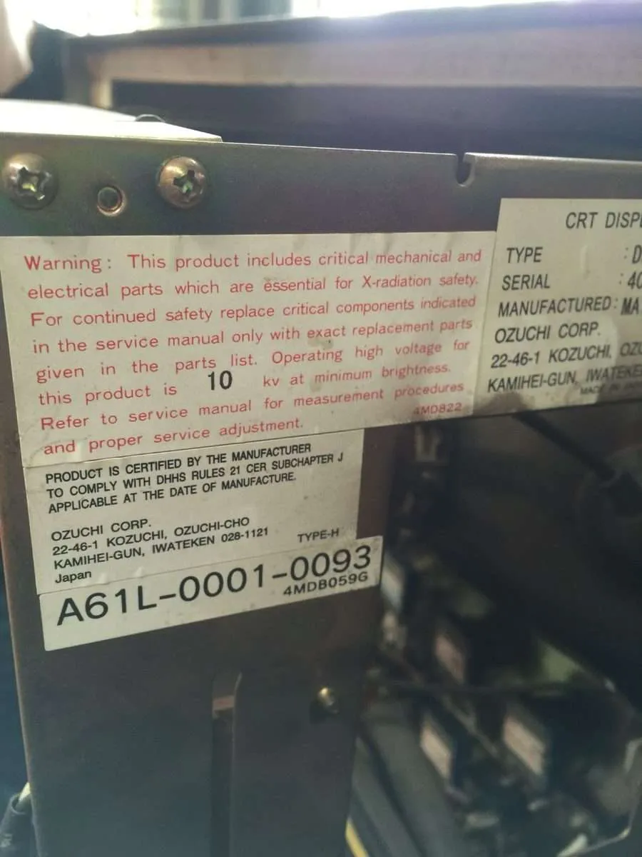
FANUC A61L-0001-0093 Original 9-inch Monochrome CRT Display (Typical Aging State After 8-10 Years)
In FANUC CNC systems, the A61L-0001-0093 is one of the most widely deployed 9-inch monochrome CRT display models, extensively paired with FANUC 0 series, 0i series, and OM-D mainstream CNC controllers. This model uses cathode ray tube technology with a designed lifespan of approximately 15,000 hours. Currently, a large number of in-service units have far exceeded their design life, with frequent failures including brightness degradation, screen blurring, and image flickering.
Kongto Technology, leveraging over a decade of industrial display retrofit experience, introduces the A61L-0001-0093 dedicated LCD upgrade module — delivering true plug-and-play replacement: no wiring changes, no parameter adjustments, no structural modifications. This guide covers the complete upgrade workflow across four stages: product identification, signal connection, physical installation, and results demonstration.
Before You Replace: Diagnose the Fault
Before spending on a replacement, confirm the CRT itself is the fault. Many "dead display" callouts turn out to be a loose cable, a blown fuse, or a mainboard issue —none fixed by a new screen. Work through the checklist below before you condemn the tube.
Common CRT Aging Symptoms
- Gradual dimming: An aged tube loses roughly 40% of its brightness over its 15,000-hour life; units past 12 years typically sit below 35% brightness —the point where a flashlight no longer helps.
- Poor focusing: Blurred character edges and distortion make offsets and programs hard to read during programming.
- Flickering and jitter: Aging high-voltage circuits cause image instability and operator fatigue during prolonged use.
- Burn-in / ghosting: Permanent phosphor damage from static screens —irreversible on a CRT.
Quick Decision Tree
- Does the control power on? If not, check the AC supply, fuse, and PSU first —a dead PSU means no clean 24V reaches the display.
- Is the display indicator on? If dark, reseat the HONDA 20-pin and DC 24V leads —a half-seated connector mimics a dead tube.
- Is brightness present? Good power rails but a dim or dark screen points to the tube itself.
- Is the image normal? Bright but garbled or missing picture points to the CNC or software, not the display.
- Is sync stable? Vertical or horizontal roll means HSYNC/VSYNC trouble; if the cable checks out and sync won't lock, replace the display.
Step 1: Product Model Identification and Verification
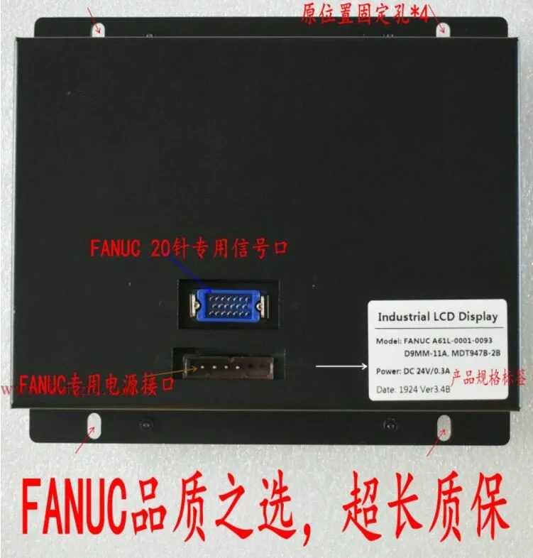
Before replacing the display, the first task is to confirm that the currently installed CRT model is indeed the A61L-0001-0093. The model label is located on the side or rear nameplate of the display housing.
Verification Checklist
- Check the label: The nameplate clearly shows "A61L-0001-0093" along with the FANUC original part number KF-M7099H
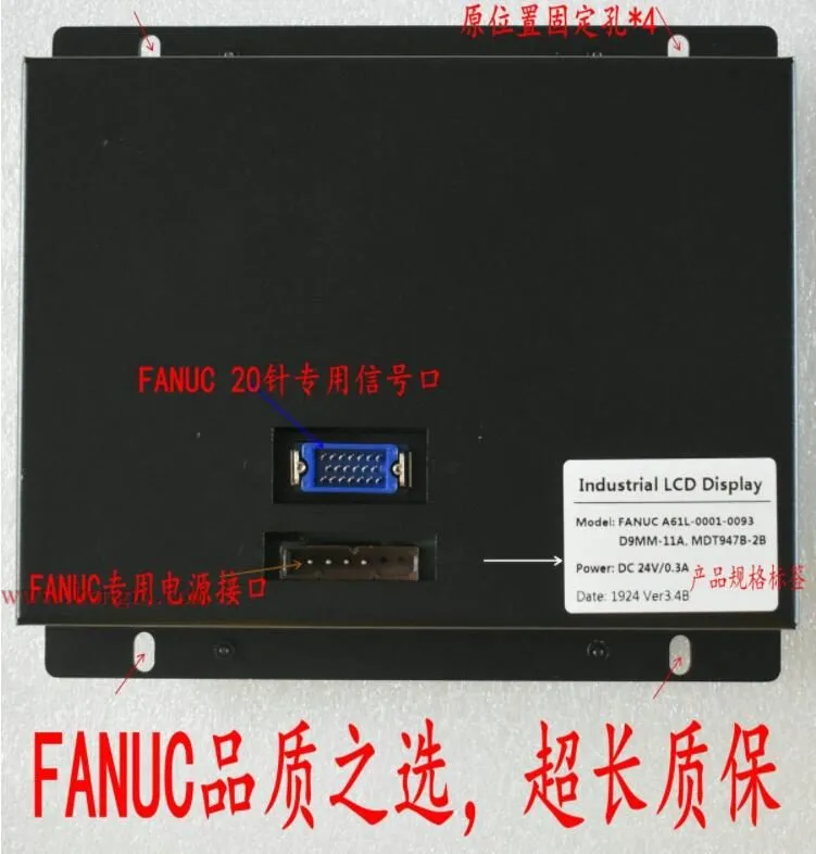
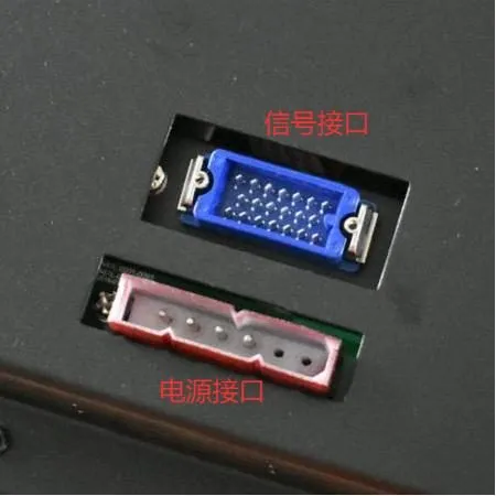
- Verify the connectors: Rear panel has a HONDA 20-pin signal connector + DC 24V 2-pin power connector
- Confirm dimensions: 9-inch monochrome CRT, standard square-frame housing, four-corner screw mounting
- Exclude similar models: A61L-0001-0090 / 0086 / 0074 appear similar but have different connectors and resolutions — do not confuse
OEM-Equivalent and Cross-Reference Codes
The A61L-0001-0093 is cross-referenced under several OEM and third-party codes. Any of the following on the tube label or a quote identifies the same 9-inch amber unit:
- KF-M7099H —the most common OEM-equivalent code, printed on the original nameplate
- MDT947B-2B —cross-reference part code for the same 9-inch unit
- D9MM-11A —variant designation within the same 9-inch family
- TX-901AB —third-party equivalent designation
Note: the A61L-0001-0095 is a 9-inch CGA/EGA variant and the A61L-0001-0094 is a 14-inch unit —different signal families, not direct swaps. Confirm the original tube label (Model / KF-M7099H, see figure below) before ordering.
Kongto LCD Upgrade Module Identification
After confirming the old CRT model, take out the Kongto Technology A61L-0001-0093 dedicated LCD upgrade module and verify the following features:
- Front: Industrial-grade TFT-LCD panel with reinforced glass protective screen, OSD menu control buttons below
- Rear: HONDA 20-pin compatible signal connector + DC 24V power connector — 100% compatible with original CRT
- Housing dimensions identical to original CRT — zero mounting hole deviation
- Module bears Kongto Technology brand label and model identification
Step 2: Signal and Cable Connection Guide
Signal connection is the most critical technical aspect of the entire upgrade. The good news: the Kongto LCD upgrade module uses exactly the same pinout as the original CRT — signal and power cables are one-to-one direct connections. No adapters, no wire cutting, no jumpers required.
2.1 Connector Comparison
| Connector Type | Original CRT | Kongto LCD Module |
|---|---|---|
| Signal Connector | HONDA 20-pin Female | HONDA 20-pin Male (Direct Plug) |
| Power Connector | DC 24V 2-pin Terminal (from CNC host) | DC 12V-24V Wide Input (Auto-adapting) |
| Video Signal | Composite Video (Monochrome) | Auto-detect, all signal formats compatible |
| Chassis Ground | Screw Ground | Screw Ground (Identical) |
2.2 Physical Interface Comparison
2.3 Signal Compatibility —Why It's Plug-and-Play
Engineers reasonably worry that an LCD won't "speak" the old CRT's video language. With this module it does, and here is the technical reason.
The HONDA 20-pin connector (HRS blue shell) carries everything the display needs: GND, R, G, B, INTENSITY, HSYNC, VSYNC, and DC 24V. There is no separate video board, external scaler, or LVDS bridge to wire —the Kongto LCD accepts that exact pinout on the same connector.
FANUC 9-inch CRTs in the A61L-0001-009X family use TTL/RGB (CGA) monochrome signaling at a line frequency of ~15.7 kHz and a frame rate of 50-60 Hz. The native CRT resolution is 640×400, accepting up to 640×480 over RGB. The Kongto panel converts that old signal path internally (TTL/RGB → VGA → TFT-LCD) and upscales to 800×600 on a modern TFT panel.
Because the conversion happens entirely inside the module, the CNC mainboard still outputs the same HONDA 20-pin TTL/RGB it always did —no parameter to edit, no video mode to select, no handshake. Machine parameters, offsets, and programs stay exactly as they are.
Step 3: Physical Installation Procedure
The entire physical installation takes approximately 30 minutes and requires only a Phillips screwdriver. Follow these detailed steps:
1 Power Off
- Turn off the CNC system main power and confirm the electrical cabinet power indicator is off
- Wait at least 5-10 minutes for the CRT high-voltage anode residual charge to bleed off (see safety note below)
- If available, use a multimeter to verify zero voltage at power terminals before proceeding
2 Remove Old CRT
- Use a Phillips screwdriver to remove the 4 corner mounting screws from the display bezel
- Carefully remove the CRT display from its mounting position — note the CRT is heavy (approx. 2-3 kg), support the bottom with one hand
- Disconnect the rear HONDA 20-pin signal cable — press the latch to release, then pull straight out
- Disconnect the DC 24V 2-pin power cable
- Keep the removed screws safely — they will be reused for the new module
3 Install LCD Upgrade Module
- Place the Kongto LCD module into the original CRT mounting position, aligning all four mounting holes
- The LCD module housing has foolproof alignment tabs — it will not fit if oriented incorrectly
- Tighten the four corner screws with moderate force — do not overtighten
4 Connect Cables
- Align the HONDA 20-pin signal cable with the LCD module rear signal port — a "click" from the latch confirms proper seating
- Insert the DC 24V 2-pin power cable into the corresponding power connector
- Verify both connectors are fully locked in place
5 Power On and Test
- Restore CNC system main power and power on
- The LCD module will automatically detect the signal and display — no parameter configuration required
- Use the OSD menu buttons on the LCD front panel to fine-tune brightness, contrast, and screen position for optimal display
Step 4: Results — Before and After
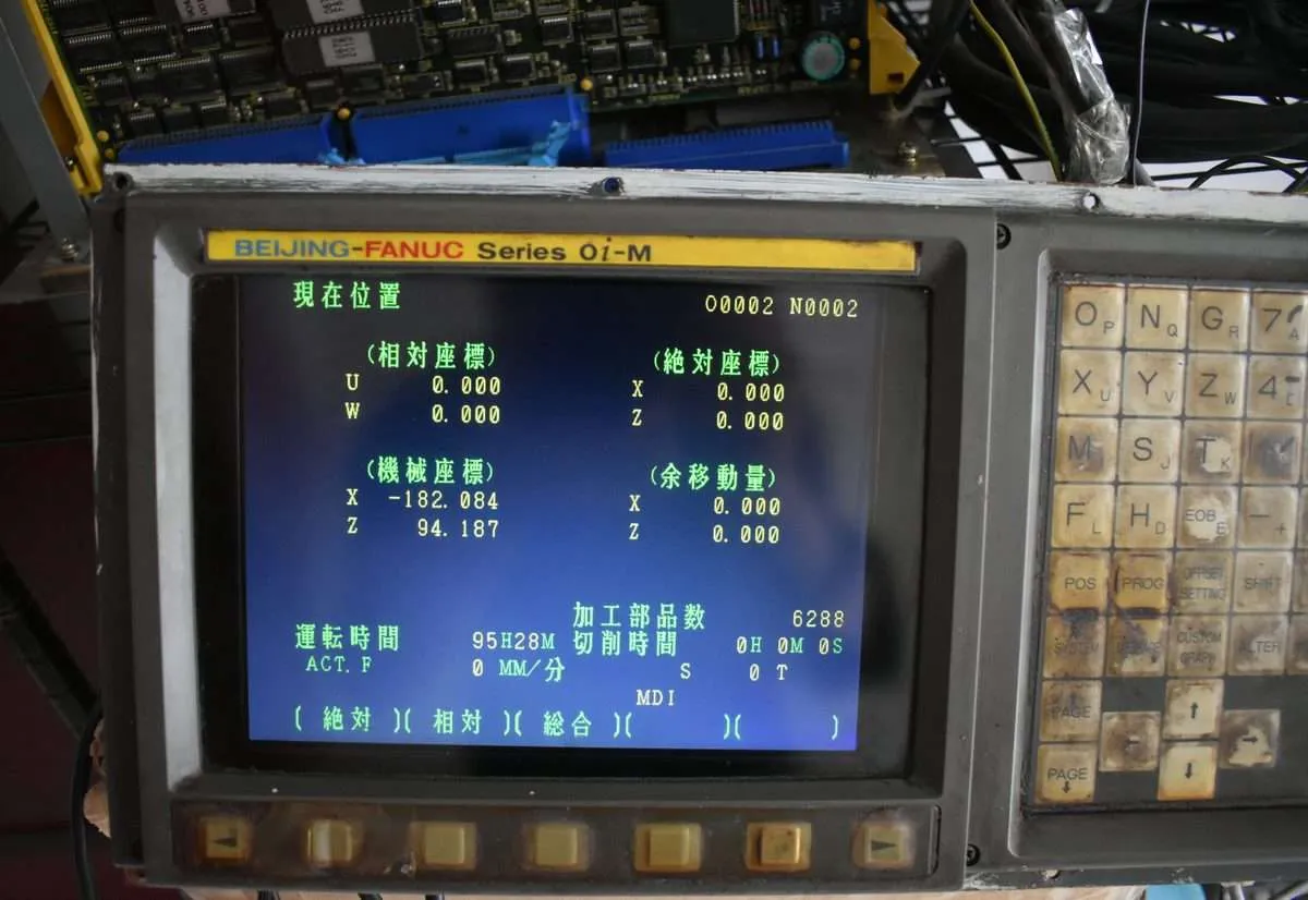
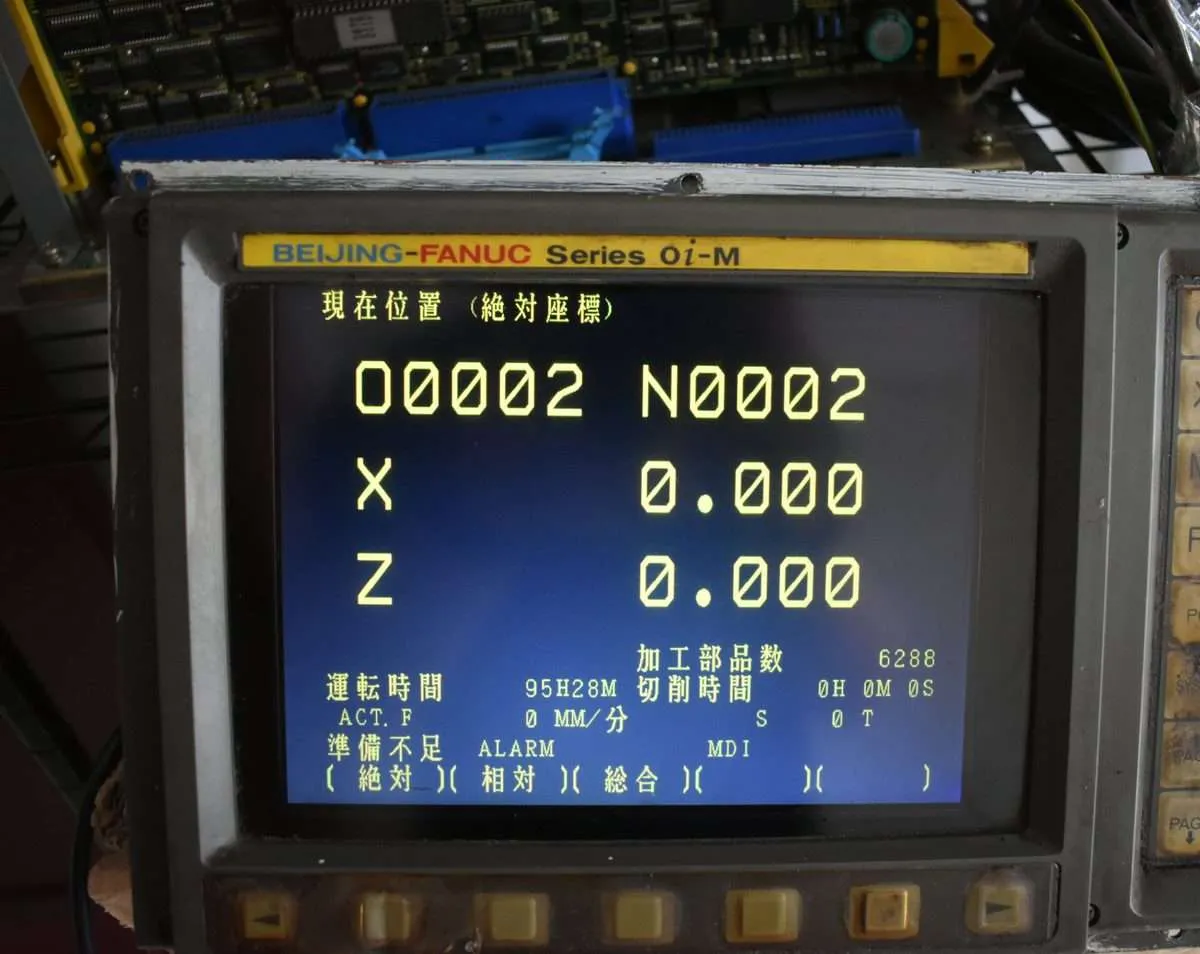
After completing the LCD upgrade, the display quality shows a dramatic improvement over the original CRT.
4.1 Display Quality Comparison
| Parameter | Original CRT | Kongto LCD After Upgrade |
|---|---|---|
| Brightness | 200 cd/m² (new); severe degradation with age | 350-450 cd/m²; long-term stability |
| Image Clarity | Blurred character edges when focus drifts | Pixel-level sharpness, no ghosting or fringing |
| Flicker | 50Hz refresh rate causes noticeable flicker | Zero flicker, comfortable for extended operation |
| Resolution | 640×400 | 800×600 (higher definition) |
| Power Consumption | 25-30W | 8-12W (approx. 60% reduction) |
| Service Life | ~15,000 hours | ≥ 50,000 hours |
| Safety | 10-15kV flyback transformer leakage risk | Low-voltage DC 24V power, zero high-voltage risk |
4.2 Power-On Verification Checklist
- ✓ Screen powers on normally — no black screen, no artifacts
- ✓ Characters display sharp and clear — no blurring, no ghosting
- ✓ No flickering or jittering
- ✓ OSD menu accessible and fully functional
- ✓ All CNC system functions operating normally — no alarm messages
System Compatibility
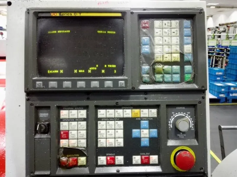
This LCD upgrade solution is compatible with the following FANUC CNC systems (all models originally equipped with the A61L-0001-0093 CRT display):
| System Series | Compatible Models | Typical Applications |
|---|---|---|
| FANUC 0 Series | 0 / 0-Mate / 0-TMate | Lathes, Mills, Grinders |
| FANUC 0i Series | 0i-A / 0i-B / 0i-C / 0i-D | Machining Centers, Lathes |
| FANUC 16i/18i/21i | 16i / 18i / 21i All Models | Mid-to-high-end Multi-axis Machining |
| FANUC OM Series | OM-D / OM-C | Mold Making, Milling |
| Machine Types | Machining centers, CNC lathes, milling machines, grinders, boring machines — any machine equipped with 0093 CRT | |
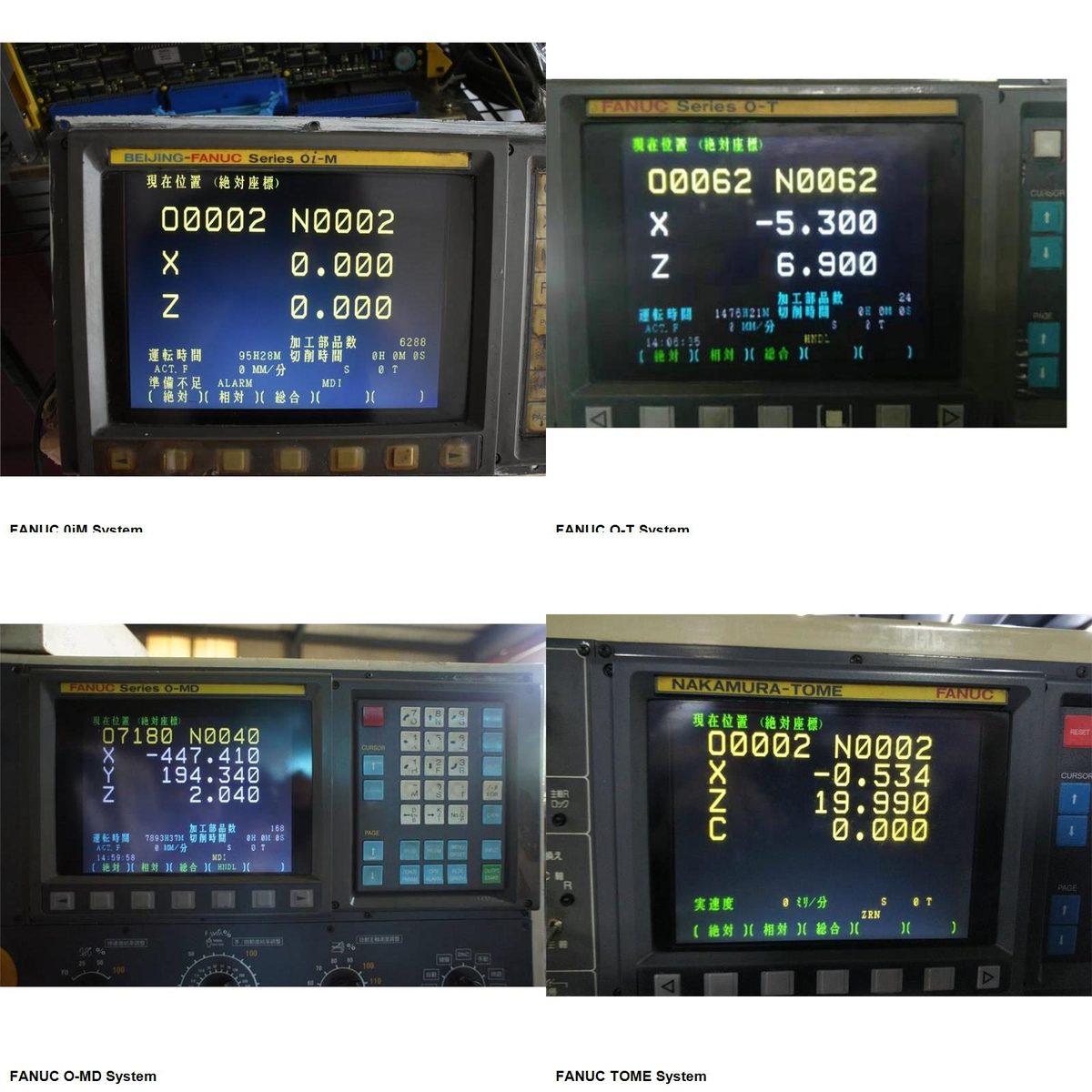
Compatibility Verified Across Tested Platforms
Beyond the system list above, the A61L-0001-0093 LCD replacement kit has been tested and validated on specific FANUC control platforms:
- FANUC 0iM —the most common milling control, widely used in machining centers
- FANUC O-T —lathe/turning control with 9-inch monochrome CRT
- FANUC O-MD —older milling/drilling control with standard CRT interface
- FANUC TOME —specialized control variant with custom display requirements
Each test included signal compatibility verification, resolution auto-detection, power stability testing, and a 72-hour burn-in. The LCD module automatically adapts to the RGB/EGA/CGA signal output of each FANUC control version —no manual configuration or parameter changes required.
Is the LCD Upgrade Worth It? 5-Year Cost Analysis
The Kongto A61L-0001-0093 LCD upgrade module is priced at $155 with a 2-year warranty. Compare that against the alternatives over a five-year horizon:
- Repeated CRT repairs: A CRT is a 15,000-hour part, and field repairs on an aging tube recur —the tube is still heading for failure. The LCD removes recurring repair cost entirely.
- Full control replacement: Swapping an entire control because of a dead screen is dramatically more expensive once you add unit cost, labor, and downtime. A $155 display swap that avoids that is an easy call.
- Downtime risk: A dim screen that misleads an operator on a Z-offset can scrap a costly workpiece in a single shift. The LCD upgrade eliminates the dimming failure mode at the source.
Even at list price, the LCD pays for itself the moment it avoids the first CRT repair —and it eliminates recurring dimming, burn-in, and the high-voltage hazard for the rest of the machine's life.
Post-Installation Maintenance
- Check signal and power cable connections for looseness every 6 months
- Maintain proper ventilation and cooling in the electrical cabinet — avoid prolonged operation above 60°C
- Periodically recalibrate brightness and contrast to comfortable levels via the OSD menu
- If display abnormalities occur, first check the HONDA 20-pin connector for oxidation or looseness
Warranty and Service
| Service Item | Details |
|---|---|
| Warranty Period | 2-Year Free Warranty (Industry Longest) — Free replacement for non-human damage |
| Technical Support | Lifetime free phone / remote video guidance |
| Shipping | Calculated at checkout |
| Installation Resources | Free installation video tutorials and illustrated operation guides |
Contact Us
Kongto Technology Co., Ltd.
✉ Email: [email protected]
☎ Phone: +86-13686889647
🌐 Web: www.cncdisplay.com
Trust the specialists — Over 500 enterprises have completed FANUC display upgrades with us, 99% customer satisfaction rate.