Video Signal Converters in CNC Control Systems
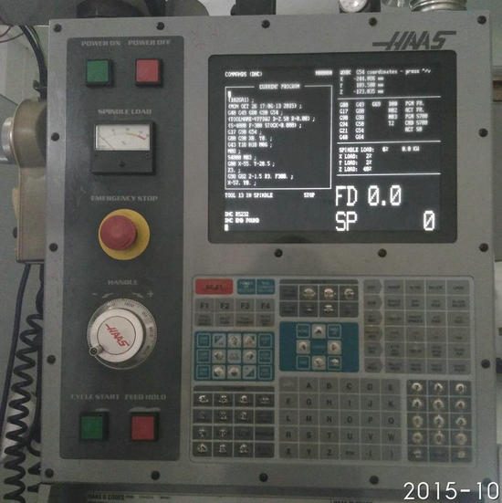
Display Overview | Source: Kongto Technology
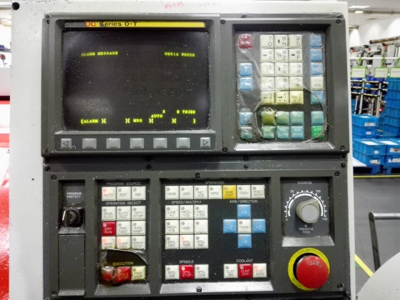
Product Photo | Source: Kongto Technology
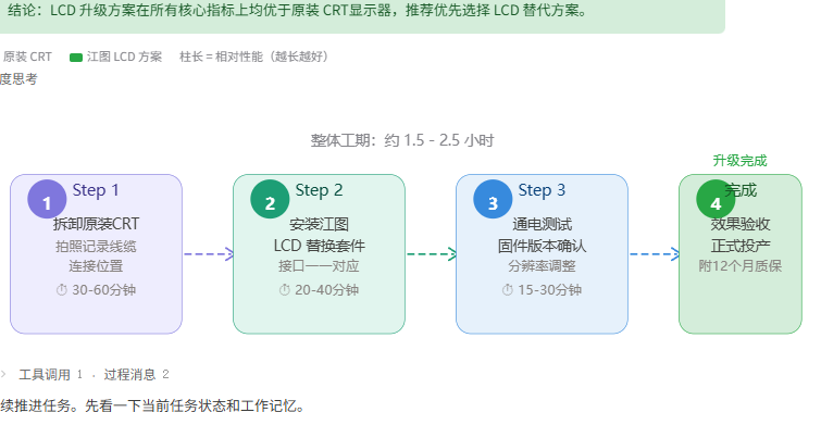
Installation View | Source: Kongto Technology
Keywords: video signal converter, CNC control system, signal conversion, industrial automation
Target Audience: CNC engineers, equipment maintenance personnel, industrial control system integrators
1. Why CNC Systems Need Video Signal Converters
Many CNC machine tools in service today were designed with display interfaces that are incompatible with modern LCD monitors. The primary scenarios requiring signal conversion include:
- CGA/EGA to VGA: Legacy CNC controllers output CGA (15kHz) or EGA (22kHz) signals that cannot directly drive VGA LCD displays
- Composite sync to separate H/V sync: Some systems output RGBS (composite sync) which must be separated into RGBHV for VGA displays
- Scan rate conversion: Converting low scan rate signals to standard VGA timing (31.5kHz+)
- Digital-to-analog conversion: TTL-level digital signals must be converted to analog VGA signals
2. Signal Types in CNC Systems
| Signal Type | Frequency | Voltage Level | Connector | FANUC Systems |
|---|---|---|---|---|
| CGA (TTL) | 15.75 kHz H / 60 Hz V | Digital 0/5V | 9-pin D-Sub | FANUC 0-M, 0-T (very early) |
| EGA (TTL) | 21.85 kHz H / 60 Hz V | Digital 0/5V | 9-pin D-Sub | FANUC 0-TC, 0-MC |
| RGBS (Analog) | 15-24 kHz H / 50-60 Hz V | Analog 0.7Vpp + Composite Sync | BNC or HONDA | FANUC 16i, 18i (some models) |
| RGBHV/VGA (Analog) | 31.5-48 kHz H / 60-75 Hz V | Analog 0.7Vpp + Separate Sync | HONDA 20-pin / HD15 | FANUC 0i, 16i, 18i |
2.1 Signal Type Comparison Table
| Signal Standard | Horizontal Frequency | Vertical Frequency | Sync Type | Max Resolution | Color Depth |
|---|---|---|---|---|---|
| CGA | 15.75 kHz | 60 Hz | Composite sync (TTL) | 640 x 200 | 4 colors (16 palette) |
| EGA | 21.85 kHz | 60 Hz | Separate sync (TTL) | 640 x 350 | 16 colors (64 palette) |
| RGB (Analog) | 15-24 kHz | 50-60 Hz | Composite sync on green / separate | 640 x 480 | Unlimited (analog) |
| RGBHV | 31.5-64 kHz | 60-85 Hz | Separate H/V (TTL) | 1024 x 768 | Unlimited (analog) |
| VGA (standard) | 31.5 kHz | 60-75 Hz | Separate H/V (TTL) | 640 x 480 | 256+ (analog) |
Understanding the sync type is critical: composite sync combines horizontal and vertical timing onto a single wire, while separate sync uses dedicated H and V lines. Most industrial LCD monitors and converters expect separate H/V sync (RGBHV).
3. Converter Selection Criteria
3.1 Input/Output Compatibility
| Selection Factor | Requirement | Verification Method |
|---|---|---|
| Input signal type | Must match CNC controller output | Check controller documentation or measure with oscilloscope |
| Output resolution | Must match LCD display native resolution | Check LCD specifications |
| Refresh rate | 60 Hz minimum, compatible with CNC frame rate | Verify in FANUC system parameters |
| Scan rate handling | Line doubling for CGA/EGA input | Verify with test pattern display |
3.2 Environmental Requirements
- Operating temperature: -20°C to +70°C for workshop environments
- Power supply: 12-36 VDC wide voltage range for PLC/cabinet compatibility
- EMC compliance: IEC/EN 61326-1 Class 2 for industrial environments
- Vibration resistance: IEC 60068-2-6 for machine tool environments
- MTBF: ≥ 50,000 hours for 24/7 operation
3.3 Converter Selection Guide by CNC Brand
| CNC Brand | Common Controller Models | Output Signal | Recommended Converter | Notes |
|---|---|---|---|---|
| FANUC | 0-M, 0-T, 0-TC, 0-MC | CGA / EGA (TTL) | JTX-CVR-001 / JTX-CVR-002 | Early models use 9-pin D-Sub; newer 0i series uses RGBHV |
| FANUC | 16i, 18i, 21i, 0i-D/F | RGBHV (Analog) | JTX-CVR-003 | Sync separator required; HONDA 20-pin connector common |
| Mitsubishi | M700V, M70, E70, C70 | RGB (Analog) + composite sync | JTX-CVR-003 | Some models output 15 kHz RGB; check service manual pinout |
| Mitsubishi | M50, M64, M65, Meldas 500 | CGA / EGA (TTL) | JTX-CVR-004 | Dual-input auto-detect recommended; verify sync polarity |
| Siemens | Sinumerik 810D, 840D | TTL RGB + VSYNC | JTX-CVR-005 | 6-bit parallel RGB; JTX-CVR-005 provides needed DAC |
| Siemens | Sinumerik 828D, 840D sl | DVI / LVDS (digital) | N/A (direct LCD) | Newer models use digital interface; no converter needed |
Always confirm your specific controller revision and output connector pinout before purchasing a converter. FANUC and Mitsubishi used multiple connector standards across production years. Request a wiring diagram from Kongto Technology when ordering.
4. Installation Best Practices
- Pre-installation: Document all existing cable connections and system parameters before making any changes
- Power isolation: Always power down the CNC machine before connecting or disconnecting display cables
- Cable routing: Route signal cables away from motor power cables and servo drives to minimize EMI
- Grounding: Ensure proper grounding of the converter to prevent ground loops and signal noise
- Vibration mounting: Secure the converter with vibration-dampening mounts inside the electrical cabinet
- Labeling: Label all connections and document the converter model and settings for future maintenance
4.1 Installation Checklist
| Step | Task | Tool Required | Time Estimate | Notes |
|---|---|---|---|---|
| 1 | Power down and lockout/tagout the CNC machine | Lockout kit, voltage tester | 5 min | Verify zero energy state before proceeding |
| 2 | Remove existing CRT display and document all cable connections | Screwdriver set, camera | 15 min | Take photos of all connectors before disconnecting |
| 3 | Identify CNC controller video output signal type and pinout | Multimeter, oscilloscope (optional) | 10 min | Measure H/V sync levels; TTL = 0-5V, analog = 0.7Vpp |
| 4 | Mount converter inside electrical cabinet using DIN rail or bracket | DIN rail clip, screwdriver | 10 min | Keep away from drive inverters and high-current cables |
| 5 | Connect input cable from CNC controller to converter | Crimping tool (if custom cable needed) | 10 min | Use shielded twisted-pair cable for analog RGB signals |
| 6 | Connect converter output to LCD monitor; power on and test | None | 5 min | If no display, check sync polarity switches on converter |
| 7 | Adjust display position, size, and phase; secure all cables | Small flathead screwdriver (for trim pots) | 10 min | Use built-in test pattern if available; document final settings |
5. Step-by-Step Installation Guide
Follow these numbered steps to perform a complete CNC CRT-to-LCD video signal converter installation. This guide assumes the correct converter model has already been selected based on your CNC controller's output signal type.
- Prepare the Workspace and Tools. Gather all necessary tools: a multimeter for voltage verification, screwdrivers (Phillips and flathead), cable ties, a crimping tool for custom cable ends, a DIN rail mounting clip (if your converter supports DIN rail mounting), and a digital camera to document original connections. Ensure adequate lighting inside the electrical cabinet.
- Perform Electrical Safety Lockout. Shut down the CNC machine using the main power disconnect. Apply a lockout/tagout device and verify zero voltage at the controller power supply terminals using your multimeter. Wait at least 3 minutes for internal capacitors to discharge. Never rely on the machine's power switch alone.
- Identify and Document the Existing Display Connections. Remove the CRT display bezel or access panel. Photograph every cable and its connector before disconnecting anything. Note the cable colors and pin positions —many CNC controllers use custom wiring that does not follow standard color codes. Check the controller model number against known pinout diagrams from Kongto Technology's compatibility matrix.
- Verify the Video Signal Parameters. With the machine powered on (after lockout is lifted for testing), use an oscilloscope to measure the H-sync frequency and V-sync frequency at the controller's video output connector. Confirm the signal matches the specifications listed in Section 2. If using a TTL-level signal (0-5V), ensure your converter is configured for TTL input; if analog (0.7Vpp RGB), set the converter accordingly.
- Mount the Converter and Route Cables. Install the converter inside the electrical cabinet using the provided DIN rail clip or mounting bracket. Keep at least 10 cm (4 inches) of separation between video signal cables and motor power cables or servo drive cables to prevent electromagnetic interference. Use shielded twisted-pair cable for the RGB signal lines, with the shield grounded at one end only to avoid ground loops.
- Connect and Power On for Initial Test. Connect the CNC controller's video output to the converter input, and the converter output to the new LCD monitor. Apply power and observe the display. If no image appears, check the converter's sync polarity DIP switches —some FANUC and Mitsubishi controllers output negative-going sync pulses that must be matched. If the image rolls vertically, adjust the V-hold or switch between composite and separate sync modes.
- Fine-Tune and Secure the Installation. Use the converter's on-board potentiometers (if equipped) or OSD menu to adjust horizontal position, vertical position, image size, and phase/clock to achieve a sharp, stable display. Run the CNC machine through a complete boot cycle and test a sample program to confirm the display remains stable under load. Secure all cables with cable ties, label both ends of each cable, and close the cabinet.
6. Kongto Technology Converter Product Line
| Model | Input | Output | Key Features | Price |
|---|---|---|---|---|
| JTX-CVR-001 | CGA (15kHz) | VGA (31kHz) | Auto line-doubling, plug-and-play | CNY 850 |
| JTX-CVR-002 | EGA (22kHz) | VGA (31kHz) | Auto line-doubling, wide voltage | CNY 880 |
| JTX-CVR-003 | RGBS | RGBHV/VGA | Sync separator, adjustable position | CNY 750 |
| JTX-CVR-004 | CGA+EGA (dual) | VGA | Auto-detect input type | CNY 950 |
| JTX-CVR-005 | TTL RGB | VGA | 6-bit DAC, supports 64 colors | CNY 720 |
All models feature: -20°C to +70°C operating range, 12-36 VDC power, MTBF ≥ 50,000 hours, CE/UL certified.
Contact Kongto Technology at [email protected] for technical consultation.