Key Color & Scanning Technologies in Industrial Video Architecture
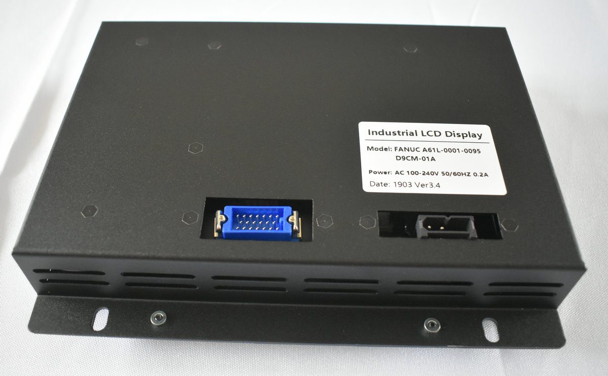
Display Overview | Source: Kongto Technology
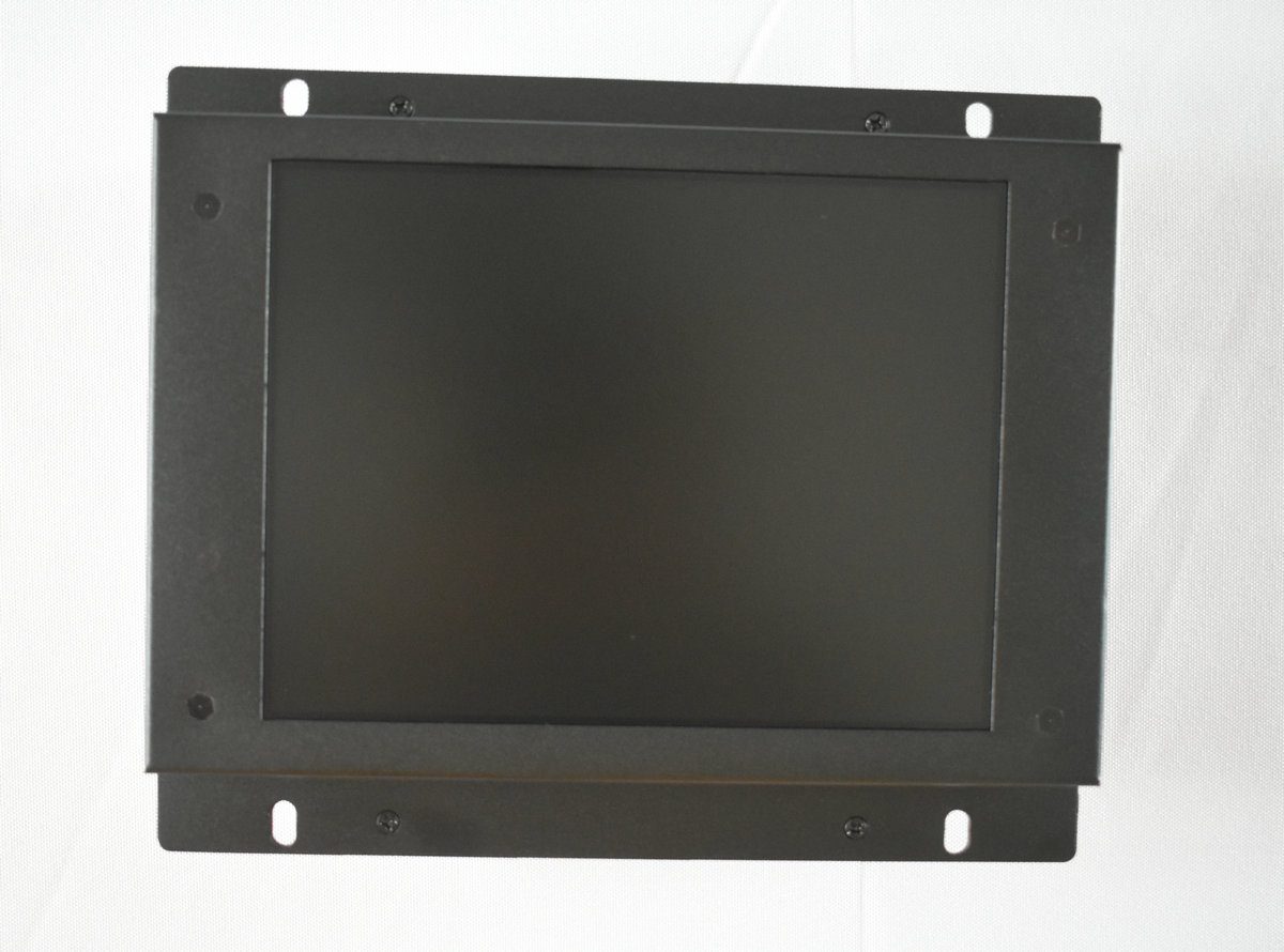
Product Photo | Source: Kongto Technology
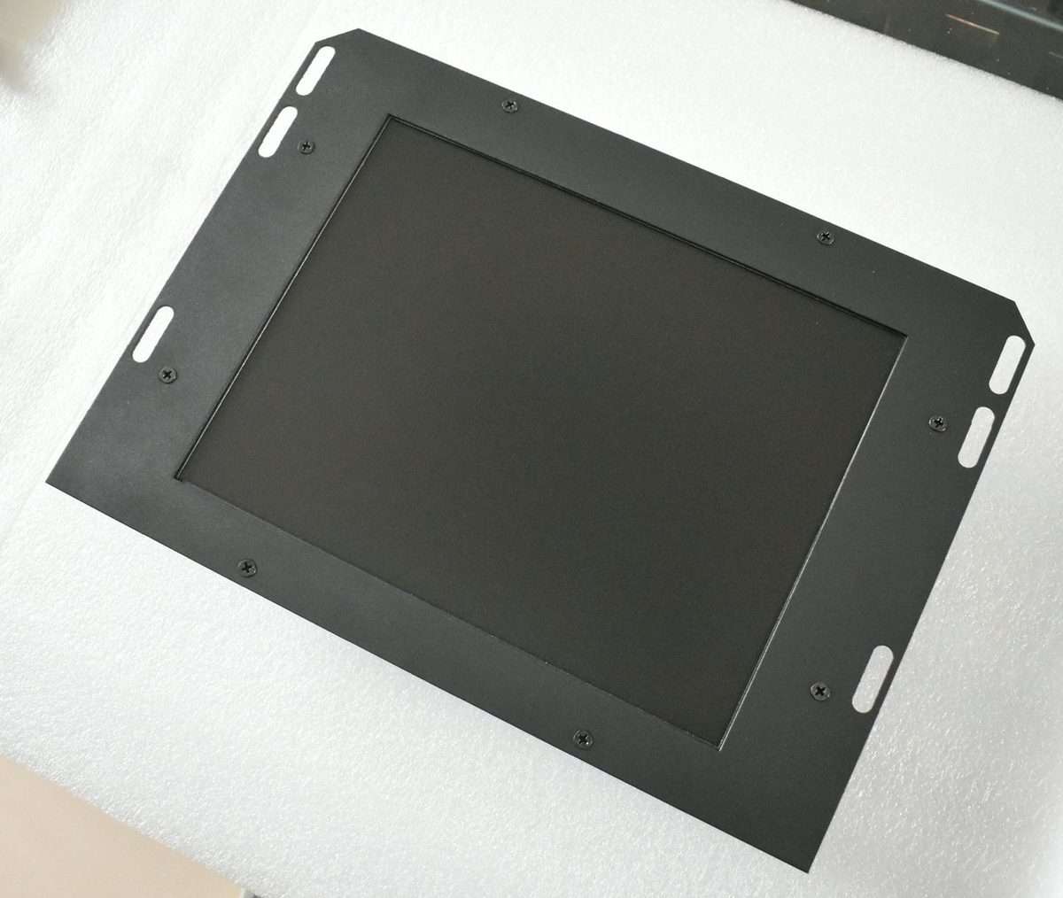
Installation View | Source: Kongto Technology
Keywords: industrial video display, color reproduction, scanning technology, CRT vs LCD
1. Color Reproduction in Industrial Displays
1.1 Color Space Standards
| Color Space | Application | Color Gamut | Bit Depth |
|---|---|---|---|
| sRGB | Standard industrial displays | ~35% of CIE 1931 | 8-bit (16.7M colors) |
| Adobe RGB | Color-critical applications | ~50% of CIE 1931 | 10-bit (1.07B colors) |
| NTSC | Legacy video systems | ~54% of CIE 1931 | 8-bit |
| CGA Palette | Legacy CNC controllers | 16 fixed colors | 4-bit |
1.2 CRT vs LCD Color Reproduction
| Feature | CRT | LCD |
|---|---|---|
| Color Generation | Phosphor excitation by electron beam | White backlight through color filters |
| Color Accuracy | Excellent native gamut, degrades with phosphor aging | Good with LED backlight, gamut limited by filter design |
| Color Consistency | Varies across screen (convergence drift) | Uniform across panel |
| Calibration Stability | Requires frequent recalibration | Stable after initial calibration |
| Viewing Angle Impact | Minimal color shift | Color shift at extreme angles (older panels) |
2. Scanning Technologies
2.1 How Video Scanning Works
Video scanning is the process by which a display system converts an electrical video signal into a visible image by tracing a series of horizontal lines across the screen. In a CRT display, a focused electron beam sweeps from left to right across the phosphor-coated screen, modulating its intensity based on the incoming video signal. At the end of each line, the beam performs a horizontal retrace —rapidly returning to the left edge —while advancing downward by one line step for the next pass. When the beam reaches the bottom-right corner, a vertical retrace returns it to the top-left to begin the next frame.
The horizontal deflection circuit controls the line-by-line sweep, while the vertical deflection circuit controls the field/frame rate. These two timing domains are synchronized by the video source via separate horizontal sync (HSYNC) and vertical sync (VSYNC) signals, or a combined composite sync (CSYNC) signal. The frequency at which these circuits operate determines the total number of lines resolvable and directly impacts the maximum image resolution the display can handle.
In modern LCD panels, the same raster-scan principle is emulated digitally: the timing controller (TCON) reads pixel data row by row from the frame buffer and addresses each row of TFT transistors sequentially, charging each pixel's liquid crystal cell to the required voltage. Instead of an electron beam sweeping physically, the LCD scans electronically by clocking data into row drivers that enable one gate line at a time, while column drivers simultaneously load the video data for that row.
The fundamental difference is that CRT scanning is analog and continuous —the beam traces a continuous path and any timing drift causes visible geometry distortion —whereas LCD scanning is digital and discrete —each pixel is addressed individually and the image is inherently stable regardless of timing jitter within the pixel clock window.
2.2 Interlaced vs Progressive Scan
Interlaced scanning: Draws odd-numbered lines first (odd field), then even-numbered lines (even field). Common in older CRT displays operating at 50/60 Hz field rate (25/30 Hz frame rate).
Progressive scanning: Draws all lines in sequence each frame. Used in virtually all modern LCD displays. Provides smoother motion and clearer text display.
| Parameter | Interlaced | Progressive |
|---|---|---|
| Frame Rate | 25/30 fps (50/60 fields/s) | 60-85 fps |
| Motion Artifacts | Combing, flicker on horizontal edges | None |
| Text Clarity | Poor (flickering) | Excellent |
| Bandwidth | Half of equivalent progressive | Full bandwidth required |
2.3 Scanning Frequency Table
Different display types and video standards operate at distinct horizontal scan rates. Matching the converter output to the display's timing window is critical for a stable image in industrial environments.
| Display Type / Standard | Horizontal Scan Rate (kHz) | Vertical Refresh (Hz) | Typical Resolution | Notes |
|---|---|---|---|---|
| CGA (Color Graphics Adapter) | 15.75 | 60 | 320x200 | Legacy CNC terminals, monochrome composite also at 15.75 kHz |
| EGA (Enhanced Graphics Adapter) | 21.85 | 60 | 640x350 | Often paired with TTL RGBI signals |
| VGA (Video Graphics Array) | 31.47 | 60-85 | 640x480 | Most widely supported industrial resolution |
| SVGA (Super VGA) | 37.9-48.9 | 60-85 | 800x600 to 1024x768 | Common on late-model CNC HMIs |
| XGA | 48.4-56.5 | 60-75 | 1024x768 | Modern industrial panel standard |
| SXGA | 60.0-68.7 | 60-75 | 1280x1024 | High-resolution automation HMIs |
| UXGA | 75.0-81.1 | 60 | 1600x1200 | Advanced visualization systems |
| HD Ready (720p) | 37.5-45.0 | 50-60 | 1280x720 | Progressive scan, common in video wall inputs |
| Full HD (1080p) | 67.5 | 60 | 1920x1080 | High-definition industrial monitors |
2.4 Scan Rate Standards
| Standard | Horizontal (kHz) | Vertical (Hz) | Resolution | Typical Use |
|---|---|---|---|---|
| CGA | 15.75 | 60 | 320x200 | Legacy CNC terminals |
| EGA | 21.85 | 60 | 640x350 | Upgraded CNC displays |
| VGA | 31.5 | 60-85 | 640x480 | Standard industrial displays |
| SVGA | 37.9-48.9 | 60-85 | 800x600-1024x768 | Modern CNC HMI |
3. Color Depth Comparison
Color depth determines how many distinct colors each pixel can display. Higher bit depth means smoother gradients and more accurate color reproduction, at the cost of increased memory bandwidth and processing requirements.
| Color Depth | Bits per Pixel | Total Colors | Typical Use Cases | Visible Banding |
|---|---|---|---|---|
| Monochrome | 1 | 2 (black/white) | Legacy CNC status displays, text terminals, single-color alphanumeric HMIs | N/A |
| Grayscale | 4-8 | 16-256 shades | Medical imaging (X-ray previews), monochrome CRT replacements, barcode readers | Noticeable in gradients at 4-bit |
| EGA / CGA Color | 4 | 16 | Early CNC controller interfaces, simple status panel graphics | Severe —only discrete color blocks |
| High Color | 15-16 | 32,768-65,536 | Basic industrial HMIs, OSD menus, lower-cost display upgrades where gradient smoothness is not critical | Visible in smooth gradients |
| True Color (8-bit) | 24 | 16,777,216 (16.7M) | Modern CNC HMIs, SCADA systems, quality inspection displays, video playback | None in most content |
| Deep Color (10-bit) | 30 | 1,073,741,824 (1.07B) | Color-critical inspection, medical-grade monitors, broadcast reference displays, HDR industrial panels | None —smooth gradients even in demanding content |
4. Display Technology Comparison for Industrial Use
Selecting the right display technology for an industrial environment involves trade-offs in brightness, viewing angle, response time, power consumption, and longevity.
| Parameter | CRT | TFT LCD | LED (Direct View) | OLED |
|---|---|---|---|---|
| Brightness (cd/m²) | 80-150 (dims with age) | 250-1500 (backlight dependent) | 2000-10000+ | 200-1000 (peak) |
| Contrast Ratio | 10,000:1 (true black) | 1000:1-5000:1 (typical) | 5000:1 (module dependent) | Infinite (per-pixel off) |
| Viewing Angle | 170°+ (no shift) | IPS: 178°; TN: 140° | 120-160° | 178°+ |
| Response Time | <1 ms (instant phosphor decay) | 4-25 ms (gray-to-gray) | <1 ms (microLED) | 0.1-1 ms |
| Lifespan (hours) | 20,000-50,000 (phosphor fade) | 50,000-100,000 (backlight) | 100,000+ | 30,000-100,000 (burn-in risk) |
| Power Consumption | 60-150 W (for 14-21") | 15-40 W (for similar size) | 30-300 W (per panel) | 20-60 W |
| Weight (17" equivalent) | 15-20 kg | 2-4 kg | Varies by pitch | 1-3 kg |
| EMI / Magnetic Sensitivity | Highly susceptible (convergence drift near motors) | Immune | Immune | Immune |
| Flicker (at 60 Hz) | Visible to sensitive users (60 Hz persistence) | None (DC backlight or PWM > 1 kHz) | None (PWM > 2 kHz typical) | None (DC drive typical) |
| Burn-in / Image Retention | Temporary (phosphor lag) | Rare (static image can cause temporary ghosting) | None | Permanent burn-in risk with static UI elements |
| Operating Temperature | 0-50°C | -20-70°C (industrial grade) | -40-85°C | 0-55°C |
| Best Industrial Application | Legacy equipment preservation | CNC replacement, HMI panels, operator terminals | Large-format digital signage, control room video walls | High-end inspection monitors, color-critical evaluation |
5. Practical Implications for CNC Display Upgrades
- When converting CGA/EGA interlaced signals to VGA progressive, the converter must perform de-interlacing and line doubling
- LCD panels have a native resolution —running at non-native resolution causes scaling artifacts. Always match converter output to LCD native resolution
- Response time matters for CNC applications: LCD panels with >8ms response time may show trailing on fast-moving tool path displays
- Input lag: Signal conversion adds 1-2 frames of latency. For CNC applications, choose converters with minimal processing delay (<16ms)
- The horizontal scan rate of the converter must fall within the LCD monitor's sync range. Most industrial LCDs accept 31-80 kHz horizontal, but some specialized panels have narrower ranges —always verify before specifying a replacement
For technical consultation on display technology selection, contact Kongto Technology at [email protected]