Industrial Controller Display Troubleshooting & Maintenance Guide
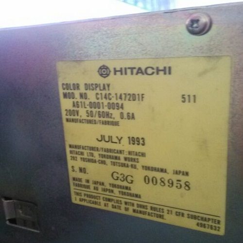
Display Overview | Source: Kongto Technology
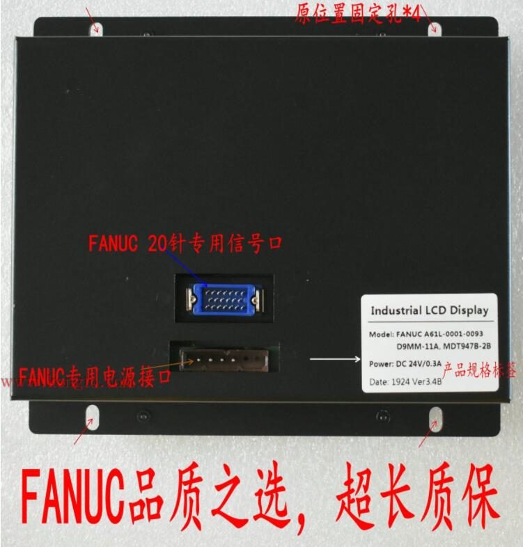
Product Photo | Source: Kongto Technology
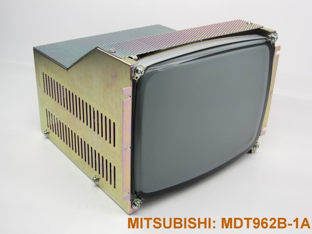
Installation View | Source: Kongto Technology
Keywords: industrial display troubleshooting, CNC display failure, preventive maintenance, display repair
Target Audience: CNC maintenance engineers, factory equipment managers, industrial automation technicians
1. Common Display Failure Categories
| Failure Type | Symptoms | Common Causes | Risk Level |
|---|---|---|---|
| No Display / Black Screen | Screen remains dark after power-on | Power supply failure, backlight failure, signal cable disconnection | Critical |
| Flickering / Intermittent | Screen flickers or intermittently goes dark | Loose connector, failing power supply capacitor, EMI interference | High |
| Color Distortion | Colors appear wrong, tint shift, or missing colors | Signal cable pin damage, graphics board failure, magnetic interference | Medium |
| Image Geometry Distortion | Image stretched, compressed, or offset | CRT aging (for CRT displays), signal timing mismatch | Medium |
| Dead Pixels / Lines | Permanent bright/dark spots or horizontal/vertical lines | LCD panel defect, driver IC failure | Low-Medium |
| Dim Display | Screen too dark even at maximum brightness | CRT phosphor aging or LCD backlight degradation | Medium |
2. Error Code Reference Table
Many CNC controllers and industrial displays report specific error codes through their diagnostic interface. The table below lists common display-related error codes and their meanings.
| Error Code | System | Meaning | Likely Cause | Solution |
|---|---|---|---|---|
| 401 | FANUC | Display unit not responding | Communication cable fault or display board power failure | Check 24V DC power to display; reseat HONDA 20-pin cable |
| 402 | FANUC | Video signal sync lost | Damaged video cable or graphics card output failure | Replace VGA/RGB cable; test with known-good signal source |
| SW0200 | Siemens 840D | OP unit: panel link error | OPI bus cable disconnected or terminating resistor missing | Verify OPI cable continuity; check bus termination |
| SW1200 | Siemens 840D | Display initialization failure | Backlight inverter fault or LCD driver board failure | Measure backlight voltage; replace inverter board if needed |
| P/S 100 | Mitsubishi M70 | CRT/LCD unit alarm | Internal display board over-temperature or voltage drop | Check cooling fan; measure 5V and 12V rails on display PCB |
| P/S 110 | Mitsubishi M70 | Video data link error | Flat-flex cable loose or damaged between controller and display | Reseat flat-flex cable; inspect for tears or bent contacts |
| EX1264 | Mazak Matrix | Display module communication timeout | RS-232/422 serial link failure to display module | Replace serial cable; check baud rate settings match |
| ALM 03 | Okuma OSP | CRT horizontal deflection fault | Horizontal output transistor shorted or flyback transformer failure | CRT models only: replace horizontal output transistor; consider LCD retrofit |
3. Systematic Diagnostic Procedure
Step 1: Visual Inspection
- Check all cable connections for looseness or damage
- Inspect display enclosure for physical damage, discoloration, or burn marks
- Verify power indicator LED status
- Check for unusual sounds (buzzing from CRT = high-voltage issue; clicking relay = power supply cycling)
- Look for bulging or leaking capacitors on exposed circuit boards
Step 2: Power Supply Testing
- Measure input voltage at the display power connector (should be 24V DC ±5%)
- Check for ripple on the power supply using an oscilloscope (should be < 100 mV p-p)
- Verify power supply current draw (excessive current = internal short circuit; too low = open circuit)
- Test under load: a healthy 10.4-inch LCD typically draws 0.8-1.2A at 24V DC
Step 3: Signal Path Verification
- Swap signal cable with a known-good cable
- Test with a different signal source (e.g., VGA test pattern generator)
- Inspect HONDA 20-pin connector pins for bending, corrosion, or pushed-back pins
- Measure signal voltage at the display input: typical RGB signals are 0.7V p-p on a 75-ohm terminated line
- Check for proper sync signal: horizontal sync should be 15-70 kHz depending on mode
Step 4: Isolation Testing
- Disconnect the display and test with a standalone monitor on the CNC signal output
- If standalone monitor works, the issue is in the original display unit
- If standalone monitor also shows issues, the problem is in the CNC graphics board or cable path
- Swap cable segment by segment: internal harness, then external cable, then adapter board
Step 5: Diagnostic Flow Table
Use the following decision table to quickly narrow down the root cause of common display failures.
| Symptom | First Check | Possible Cause | Solution |
|---|---|---|---|
| Screen completely dark, power LED off | Does any other machine component power up? | Fuse blown on display power circuit (typically 2-5A slow-blow) | Replace fuse; if it blows again, check for shorted capacitor or regulator on display PCB |
| Screen dark, power LED on steady | Shine a flashlight at an angle onto the screen | Backlight failed but LCD/CRT still receiving signal (common on LCDs >5 years old) | Check backlight inverter output voltage; replace CCFL/LED strip or inverter board |
| Screen dark, power LED blinking | Count the blink pattern and rate | Controller board fault —specific blink codes indicate memory, backlight, or panel errors | Look up LED blink code table (varies by manufacturer); replace controller board |
| Flickering image, unstable | Does flicker change with vibration (tap gently on case)? | Loose internal ribbon cable or failing connector; marginal power supply capacitor | Open display and reseat all internal connectors; replace electrolytic capacitors on PSU |
| Image present but scrambled / garbled | Is the image completely random, or does it show partial data? | Signal timing mismatch (wrong resolution/refresh); bad data line in cable; graphics card failure | Verify CNC video output timing matches display's supported range; replace signal cable |
| Vertical lines on screen | Are lines at fixed pixel positions or do they drift? | Fixed lines = LCD driver IC (COG/COF) failure; drifting = signal interference | Fixed lines: LCD panel replacement needed. Drifting: check cable shielding and grounding |
| Image too bright / washed out | Can you adjust with on-screen display menu? | Contrast voltage out of spec; CRT video amplifier transistor biasing off; LCD gamma voltage incorrect | If OSD adjustments have no effect, repair involves display PCB-level troubleshooting |
| Image shifted, cannot center | Does the image have black borders on one or more sides? | Horizontal/vertical sync polarity mismatch; CRT deflection yoke shifted; auto-adjust circuit failure | Try auto-adjust via OSD; for CRTs, adjust yoke position; for LCDs check EDID timing |
4. Common Failure Solutions
4.1 CRT Display Failures
| Failure | Solution | Cost Estimate | Recommended Action |
|---|---|---|---|
| Dim/dark CRT | Replace CRT with LCD (recommended) or replace CRT tube | CNY 800-3,500 | LCD retrofit (long-term cost savings) |
| High-voltage arcing | Replace flyback transformer (FBT) | CNY 500-1,200 | Consider LCD retrofit instead |
| Color convergence drift | Recalibrate convergence magnets on CRT yoke | CNY 200-400 | Temporary fix; will recur as CRT ages |
| No raster (no visible scan lines) | Check CRT filament glow; replace if no glow | CNY 100-300 | If CRT tube is end-of-life, LCD retrofit is more economical |
4.2 LCD Display Failures
| Failure | Solution | Cost Estimate |
|---|---|---|
| Backlight failure (CCFL/LED) | Replace LED backlight module or CCFL tube | CNY 200-500 |
| Inverter board failure (no backlight) | Replace inverter board | CNY 300-600 |
| Driver board failure (no image) | Replace driver/scaler board or entire LCD unit | CNY 500-2,000 |
| Dead pixels (clustered >5) | Replace LCD panel | CNY 1,000-2,500 |
| Touch panel unresponsive (if equipped) | Recalibrate or replace touch overlay | CNY 300-800 |
4.3 Real-World Troubleshooting Scenarios
A 2015 FANUC 0i-MD controller driving a 10.4-inch LCD displayed intermittent blackouts lasting 1-3 seconds, occurring every 15-30 minutes. The machine continued running during blackouts. Diagnostics did not log any controller alarms.
Investigation: The display power supply output was measured at 24.1V DC unloaded and 23.8V loaded, both within spec. However, an oscilloscope revealed 450 mV p-p ripple at 100 Hz on the 24V rail —well above the acceptable 100 mV p-p threshold. The ripple originated from aging filter capacitors on the machine's I/O power supply module.
Solution: Replaced the 470 uF / 50V electrolytic capacitors on the I/O power supply board. Ripple dropped to 35 mV p-p. Blackouts stopped completely. Total parts cost: under CNY 20.
After a planned power-down for maintenance, a Siemens 840D with OP010 panel displayed random characters and garbled graphics on startup. The panel communicated via OPI bus.
Investigation: The OPI bus cable was found to have a loose DB9 connector at the controller end —one of the retaining screws was missing, allowing the connector to partially disengage. This caused intermittent data corruption on the bus.
Solution: Tightened the DB9 connector (replaced missing screw with a standard M3x10mm threaded standoff). Performed a full power cycle. Display returned to normal. Preventative: applied thread-locking compound to both OPI connector screws to prevent future loosening.
A 2007 Mitsubishi M70 controller with an original 9-inch CRT display had gradually shifted to a green-dominant image over several months. The OSD color adjustments could not fully correct the issue.
Investigation: Measured the RGB drive voltages at the CRT video amplifier board. Red gun drive measured 45V instead of the expected 60V, while green was at 62V (nominal) and blue at 55V. The red drive transistor was found to have degraded, likely from thermal cycling over 18 years of near-continuous operation.
Solution: Rather than sourcing a hard-to-find 18-year-old video amplifier transistor, the customer opted for a CRT-to-LCD retrofit kit. The LCD conversion resolved the tint issue entirely, added OSD geometry controls, and eliminated the dim-brightness complaint the operator had been experiencing. Energy consumption dropped from 65W (CRT) to 18W (LCD).
An Okuma OSP-P200 lathe with a 12.1-inch LCD showed a single horizontal line of dead pixels about 3 inches from the top of the screen. The line appeared on some cold mornings but disappeared after 20-30 minutes of operation.
Investigation: The intermittent nature suggested a thermal expansion issue. The LCD panel's tab-bonded driver IC (COF —Chip-on-Flex) had a hairline crack at the bonding interface that made contact once the panel warmed up and expanded slightly.
Solution: Applying gentle pressure to the COF area with a non-conductive plastic tool temporarily restored the missing lines during testing, confirming the diagnosis. The LCD panel was replaced. The failed panel was sent for recycling. Total downtime: 2 hours.
5. Preventive Maintenance Schedule
| Task | Frequency | Details |
|---|---|---|
| Visual inspection | Weekly | Check display for flicker, color anomalies, physical damage |
| Connector check | Monthly | Verify all cable connections are secure, inspect for corrosion |
| Ventilation cleaning | Quarterly | Clean air vents and heat sinks with compressed air |
| Power supply test | Semi-annually | Measure power supply voltage and ripple at the display connector |
| Full system calibration | Annually | Calibrate display colors, brightness, and geometry |
| Backlight brightness measurement | Annually | Measure luminance with a lux meter; replace if below 70% of original spec |
6. Test Equipment Reference
The following table lists the essential test equipment for diagnosing industrial display faults and their approximate price ranges.
| Tool / Instrument | What It Measures | Typical Price Range (CNY) | Recommended for |
|---|---|---|---|
| Digital Multimeter (DMM) | Voltage, current, resistance, continuity | 100 - 800 | Basic power supply checks, fuse testing, cable continuity |
| Oscilloscope (2-channel, 50-100 MHz) | Signal waveform, ripple, timing, video signal integrity | 1,500 - 5,000 | Ripple measurement, RGB signal analysis, sync pulse checking |
| Handheld VGA/HDMI Test Pattern Generator | Outputs known-good test patterns at various resolutions | 500 - 2,000 | Isolating display panel faults from signal source faults |
| DC Power Supply (0-30V, 3-5A) | Provides substitute power for bench testing displays | 300 - 1,500 | Running displays outside the machine for isolated testing |
| ESD-Safe Tool Kit | Prevents electrostatic damage during repair | 100 - 400 | Safe handling of LCD driver boards and controller PCBs |
| Lux Meter / Light Meter | Display luminance (brightness) in cd/m² or lux | 100 - 600 | Quantifying dim display and tracking backlight degradation over time |
| Thermal Imaging Camera | Temperature distribution on circuit boards | 1,000 - 4,000 | Locating overheating components, failing regulators, and short circuits |
| Cable Tester (HONDA 20-pin / DB9 / DB15) | Pin-to-pin continuity and short detection in signal cables | 200 - 800 | Rapid cable fault verification without manual pin-by-pin testing |
| Capacitance / ESR Meter | Capacitor health (capacitance value and Equivalent Series Resistance) | 200 - 1,000 | Identifying failing electrolytic capacitors before they cause visible symptoms |
| Logic Analyzer (8-16 channel) | Digital bus signals (SPI, I2C, parallel RGB) | 500 - 3,000 | Debugging communication between controller and display driver board |
7. When to Upgrade vs. Repair
| Scenario | Recommended Action | Reasoning |
|---|---|---|
| CRT display >10 years old | Upgrade to LCD | Repair costs will accumulate; LCD offers 4-5x longer lifespan |
| Multiple CRT failures per year | Upgrade to LCD | Cost of repeated repairs exceeds LCD investment |
| LCD backlight failure (under 3 years) | Repair backlight | Cost-effective; LCD panel still has many years of service life |
| LCD panel damage | Replace LCD unit | Panel replacement cost often exceeds new unit cost |
| Display driver board failure (obsolete model) | Upgrade complete display | Obsolete driver ICs may be unavailable; complete unit replacement ensures future supportability |
For professional display maintenance and upgrade services, contact Kongto Technology at [email protected]