Industrial RGBHV Signal Analysis —From CGA/EGA to Modern Display
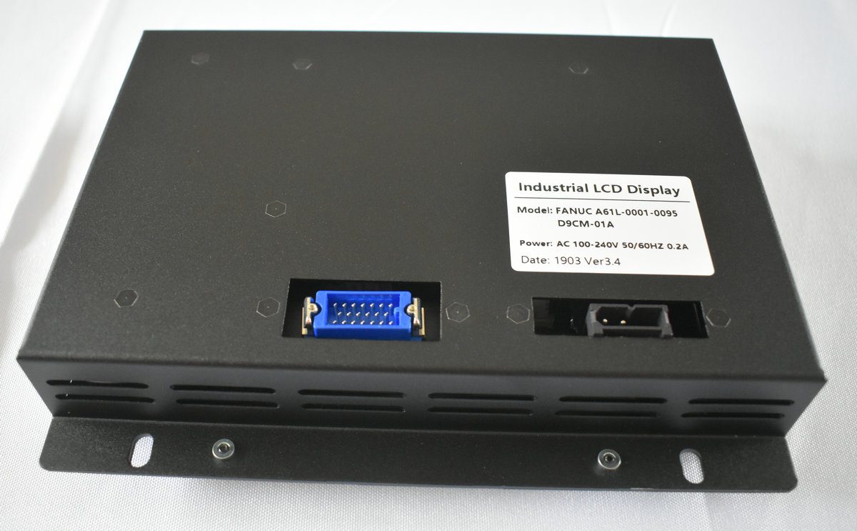
Display Overview | Source: Kongto Technology
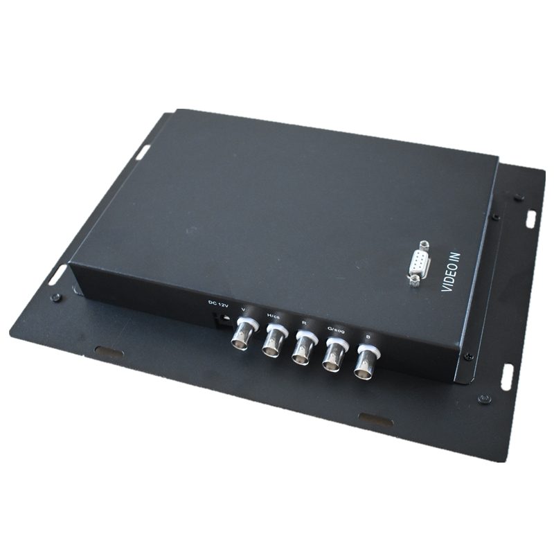
Product Photo | Source: Kongto Technology
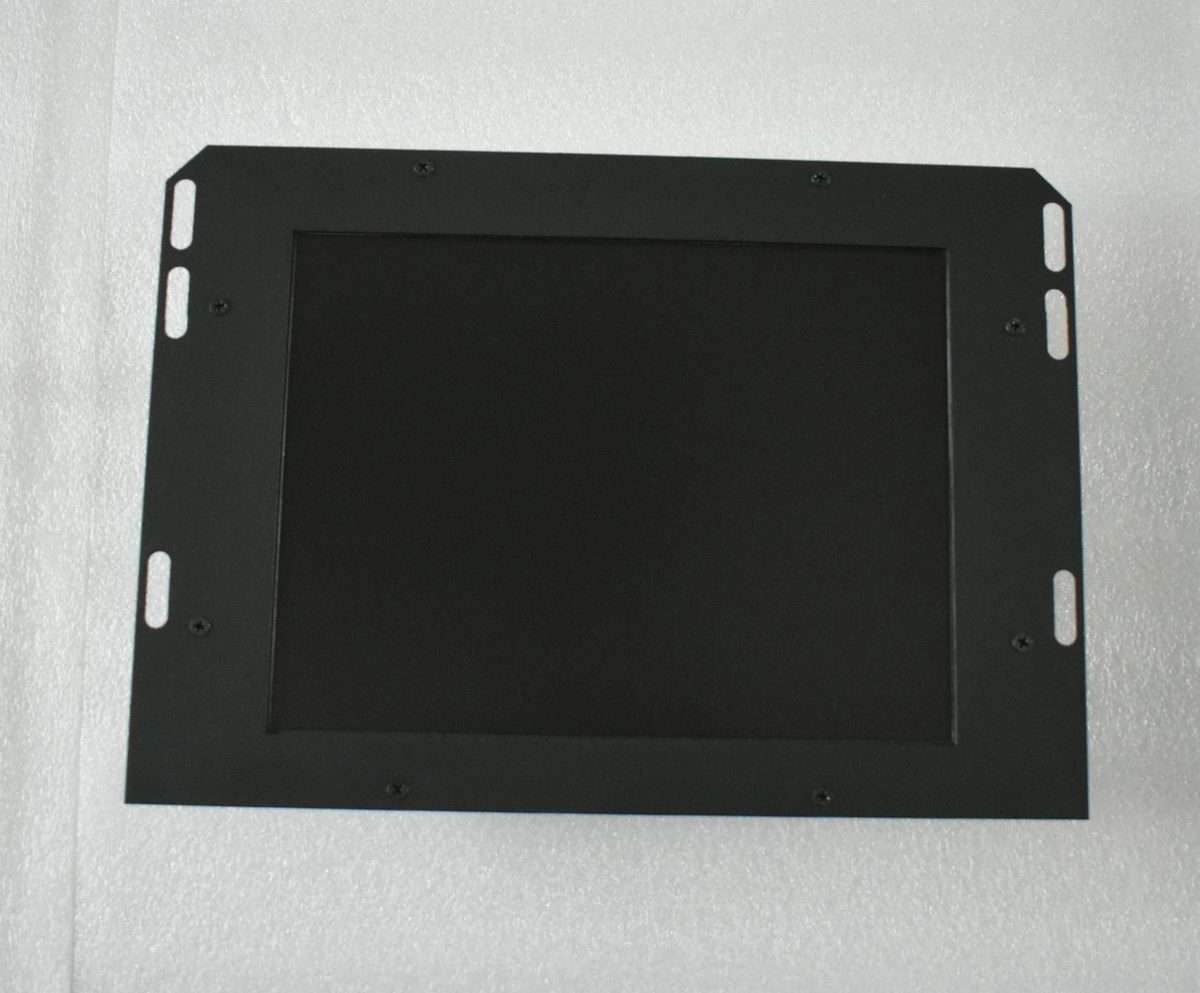
Installation View | Source: Kongto Technology
Keywords: RGBHV signal, CGA/EGA to VGA, industrial display technology, signal conversion
Target Audience: CNC engineers, industrial automation technicians, video signal system designers
1. Evolution of Industrial Video Signals
| Era | Signal Standard | Resolution | Refresh Rate | Typical Application |
|---|---|---|---|---|
| 1980s-1990s | CGA (Color Graphics Adapter) | 320x200 / 640x200 | 60 Hz | Early CNC controllers, industrial terminals |
| 1985-1995 | EGA (Enhanced Graphics Adapter) | 640x350 | 70 Hz | Upgraded CNC displays, PLC monitors |
| 1990-2005 | VGA (Video Graphics Array) | 640x480 / 800x600 | 60-85 Hz | FANUC CRT displays, industrial PCs |
| 2005-Present | SVGA/XGA Digital (DVI/HDMI) | 800x600 to 1920x1080 | 60-120 Hz | Modern LCD displays, HMI panels |
2. Understanding RGBHV Signal Architecture
2.1 What is RGBHV?
RGBHV stands for Red, Green, Blue, Horizontal Sync, Vertical Sync. It is a method of transmitting video signals using five separate channels:
- R, G, B: Three analog color channels, each carrying 0-0.7V peak-to-peak signals representing the primary colors
- H-Sync: Horizontal synchronization pulse that defines the start of each scan line
- V-Sync: Vertical synchronization pulse that defines the start of each frame
This separation provides superior signal quality compared to composite signals (CGA/EGA) because each color channel is isolated, preventing cross-talk and color bleeding.
2.2 Signal Timing Parameters
| Parameter | CGA | EGA | VGA | SVGA |
|---|---|---|---|---|
| Horizontal Frequency | 15.75 kHz | 21.85 kHz | 31.5 kHz | 37.9-48.9 kHz |
| Vertical Frequency | 60 Hz | 60 Hz | 60-85 Hz | 60-85 Hz |
| Pixel Clock | 14.3 MHz | 16.3 MHz | 25.2 MHz | 40-65 MHz |
| Color Depth | 4-bit (16 colors) | 6-bit (64 colors) | 8-bit (256 colors) | 24-bit (16.7M colors) |
| Signal Type | Digital TTL | Digital TTL | Analog 0.7Vpp | Analog 0.7Vpp |
2.3 Signal Frequency Table
| Standard | Resolution | H-Sync Freq | V-Sync Freq | Pixel Clock | H-Sync Polarity | V-Sync Polarity |
|---|---|---|---|---|---|---|
| CGA | 640x200 | 15.750 kHz | 60.000 Hz | 14.318 MHz | Positive | Positive |
| EGA | 640x350 | 21.850 kHz | 60.000 Hz | 16.257 MHz | Positive | Negative |
| VGA | 640x480 | 31.469 kHz | 59.940 Hz | 25.175 MHz | Negative | Negative |
| SVGA | 800x600 | 37.879 kHz | 60.317 Hz | 40.000 MHz | Positive | Positive |
| XGA | 1024x768 | 48.363 kHz | 60.004 Hz | 65.000 MHz | Negative | Negative |
Table: Detailed VESA-standard timing parameters for legacy and modern video signals. Sync polarity indicates whether the sync pulse is active-high (positive) or active-low (negative).
2.4 Principles of RGBHV Signal Transmission
RGBHV belongs to the family of component video standards where each signal component travels on a dedicated conductor. This architecture offers several fundamental advantages over composite or S-video formats, but it also demands strict attention to transmission-line theory.
Impedance Matching and Signal Integrity. Each RGB line is designed to drive a 75-ohm terminated load. The characteristic impedance of the transmission line (typically RG-59 coaxial cable for BNC installations or the individual twisted pairs inside a VGA cable) must match both the source output impedance and the termination impedance at the display or converter input. Mismatched impedance creates signal reflections: when the incident wave encounters a discontinuity, a portion of the energy is reflected back toward the source, interfering with subsequent signal transitions. Reflections manifest as visible ghosting, color fringing, horizontal "ringing" bars, or timing jitter —problems that are especially severe in long cable runs above 5 meters. Proper 75-ohm termination resistors at the receiving end are therefore critical for clean RGBHV transmission.
Bandwidth Requirements. The analog bandwidth required per RGBHV channel is governed by the pixel clock frequency. According to the Nyquist criterion, the transmission channel must support at least half the pixel clock frequency to preserve the fundamental harmonic of the video signal. In practice, to maintain sharp edge transitions (rise times below 5 ns), a bandwidth of 3 to 5 times the pixel clock is recommended. For VGA at 25.175 MHz pixel clock, each color channel therefore requires approximately 12.6 MHz of bandwidth for basic reproduction, but high-quality converters use video op-amps with bandwidths exceeding 100 MHz to preserve edge sharpness. For SVGA at 65 MHz, the minimum requirement rises to 32.5 MHz per channel. The total video bandwidth across all three color channels defines the system's ability to render fine text and detailed graphics demanded by industrial HMI applications.
DC Offset and Black-Level Clamping. In a properly designed RGBHV system, the black level is referenced to 0 V and the peak white level is 0.7 V above black. Each scan line begins with a blanking interval during which a DC-restoration (clamping) circuit samples the black level and adjusts the DC offset to eliminate low-frequency drift. Without this clamping, variations in the average picture level (APL) from frame to frame would cause the black level to shift —a phenomenon known as "black-level wander" or "hum" —resulting in inconsistent brightness and color saturation across the display. Sync signals in RGBHV use negative-going pulses that normally swing from 0 V to -0.3 V on dedicated sync lines, well below the black reference to prevent interference with the active video region.
Crosstalk Isolation. With five independent analog channels (R, G, B, H-Sync, V-Sync) routed in close proximity inside a VGA cable or on a PCB, capacitive and inductive coupling between adjacent conductors can introduce crosstalk —a signal from one channel leaking into another. On a VGA display, crosstalk from the H-Sync line into the Green channel, for example, appears as faint vertical bars overlaid on the image. Industry best practice requires a minimum of -40 dB isolation between any two channels at 10 MHz. This is achieved through proper shielding (individually shielded coaxial pairs for each color), careful ground-plane separation in PCB layout, and differential routing techniques that keep high-speed digital signals (the sync lines) physically separated from the analog color channels.
Rise Time and Skew Control. For clean pixel transitions, the 10%-to-90% rise time of each color channel should be below 5 ns. Excessive rise time softens edges and reduces apparent sharpness, while excessive skew (timing mismatch between the R, G, and B channels) produces color fringing at vertical edges. High-performance converters incorporate programmable delay lines to compensate for PCB trace-length differences and cable-induced skew, aligning all three color channels within 2 ns of each other at the display input.
3. CGA/EGA to RGBHV Conversion Process
3.1 Signal Type Conversion
The key challenge in converting CGA/EGA to RGBHV is the fundamental difference in signal types:
- CGA/EGA: Digital TTL signals (0V or 5V levels) —on/off for each color bit
- RGBHV/VGA: Analog signals (0-0.7V continuous) —proportional voltage for each color
A digital-to-analog converter (DAC) is required to translate TTL logic levels into proportional analog voltages. The Kongto Technology converter uses a high-speed video DAC with 8-bit resolution per channel, ensuring smooth color gradients.
3.2 Scan Rate Conversion
CGA operates at 15.75 kHz horizontal scan rate, while VGA requires 31.5 kHz. This means each CGA scan line must be doubled (line doubling) or the frame buffer must be scaled to match VGA timing. The converter handles this automatically using an integrated frame buffer and scaling engine.
3.3 Synchronization Signal Generation
CGA/EGA use composite sync (combined H+V on a single line), while RGBHV separates horizontal and vertical sync. The converter extracts and regenerates clean, separate H-Sync and V-Sync signals with proper timing.
4. Practical Conversion Solutions
| Input Signal | Output Signal | Converter Model | Key Features | Unit Price |
|---|---|---|---|---|
| CGA (15kHz) | RGBHV/VGA (31kHz) | JTX-CVR-001 | Auto-scan, plug-and-play, -20°C~+70°C | CNY 850 |
| EGA (22kHz) | RGBHV/VGA (31kHz) | JTX-CVR-002 | Auto-scan, plug-and-play, wide voltage 12-36V | CNY 880 |
| RGBS (composite sync) | RGBHV/VGA | JTX-CVR-003 | Sync separator, adjustable H/V position | CNY 750 |
| CGA+EGA (dual input) | RGBHV/VGA | JTX-CVR-004 | Auto-detect input type, dual-input switch | CNY 950 |
5. Signal Quality Verification
After conversion, verify the following signal quality metrics:
- Signal amplitude: R/G/B channels 0.7Vpp ±5% into 75Ω load
- Sync pulse width: H-Sync 3.8µs ±10%, V-Sync 64µs ±10%
- Rise/fall time: <5ns for clean edges
- Crosstalk: <-40dB between channels
- Impedance matching: 75Ω ±5% on all lines
6. RGBHV Wire Color Code and Pinout Standards
When working with RGBHV signals in industrial environments, identifying the correct wire colors and pin assignments is essential for successful cable termination and troubleshooting. The table below lists the standard VGA (DE-15) pinout and the corresponding wire color codes used in typical industrial RGBHV cables.
| Signal | VGA Pin (DE-15) | Standard Wire Color | BNC Connector Color |
|---|---|---|---|
| Red | 1 | Red | Red |
| Green | 2 | Green | Green |
| Blue | 3 | Blue | Blue |
| Horizontal Sync (H-Sync) | 13 | Yellow | Yellow |
| Vertical Sync (V-Sync) | 14 | White | White |
| Red Ground | 6 | Black (paired with Red) | BNC shield |
| Green Ground | 7 | Black (paired with Green) | BNC shield |
| Blue Ground | 8 | Black (paired with Blue) | BNC shield |
| Sync Ground | 10 | Black | BNC shield |
| DDC Data (I²C) | 12 | Green/White (if present) | N/A |
| DDC Clock (I²C) | 15 | Blue/White (if present) | N/A |
Note: In five-wire RGBHV BNC cable assemblies, each signal uses a separate coaxial cable with the shield serving as the ground return. The shield is typically connected to pin 10 (sync ground) and the chassis ground at the source end.
7. Connector Cross-Reference for RGBHV and Related Signals
Different generations of industrial display equipment use different physical connectors to carry RGBHV or related video signals. The following table helps identify which connector type corresponds to which signal standard, facilitating cable selection and adapter planning during retrofit projects.
| Signal Type | Common Connector | Pin Count | Form Factor | Typical Use |
|---|---|---|---|---|
| CGA | DE-9 | 9 (2 rows) | D-subminiature | IBM PC/XT/AT original CGA, early CNC terminals |
| EGA | DE-9 | 9 (2 rows) | D-subminiature | EGA cards and monitors (same connector as CGA) |
| VGA (RGBHV) | DE-15 (HD-15) | 15 (3 rows) | High-density D-sub | Most common PC and industrial VGA interface |
| RGBHV (BNC) | BNC (5x) | 1 per channel | Bayonet-coupled coaxial | Professional/broadcast, long cable runs, test equipment |
| RGBS (composite sync) | BNC (4x) or RCA (4x) | 1 per channel | Coaxial | Arcade monitors, legacy video walls, some PLC displays |
| DVI-I (analog + digital) | DVI-I | 29 | DVI (flat-pin + cross-pin) | Carries analog RGBHV on the same pins as VGA plus digital TMDS |
| DVI-D (digital only) | DVI-D | 24 | DVI (flat-pin only) | Digital-only output, no RGBHV analog pass-through |
| HDMI | HDMI Type A | 19 | HDMI (flat, keyed) | Digital video + audio, backward compatible via adapters |
| SCART (Europe) | SCART (Péritel) | 21 | Rectangular, shrouded | European legacy AV equipment, carries analog RGB+sync+audio |
| DisplayPort | DisplayPort | 20 | Latching rectangular | Modern packetized digital, no native analog output |
Tip: When retrofitting industrial equipment from CGA/EGA to modern displays, the most common adapter chain is CGA DE-9 → VGA DE-15 (via converter box) → DVI/HDMI (via active adapter if needed). Direct passive cable adapters between CGA/EGA and VGA will not work because of the fundamental signal-type difference (digital TTL vs. analog).
For technical consultation on signal conversion solutions, contact Kongto Technology at [email protected]